Cable structure

a cable and cable technology, applied in the direction of power cables, cables, coupling device connections, etc., can solve the problem of short circuit of cathode conduction wires

Inactive Publication Date: 2013-03-26
TAIWAN LINE TEK ELECTRONICS
View PDF6 Cites 3 Cited by
  • Summary
  • Abstract
  • Description
  • Claims
  • Application Information

AI Technical Summary

Benefits of technology

[0009]One another object of the present invention is to provide a cable structure in which a positioning sleeve is provided for increasing the insulation distance between an anode and a cathode conduction wires and is able to effectively avoid short circuit of the anode and the cathode conduction wires.
[0012]a positioning sleeve, which is a metal ring, the metal ring passes through the first conductive wire and the third conductive wire having the third insulation layer and is sleeved and riveted on the second insulation layer so that the metal ring is clamped and fastened on the second insulation layer and is served to abut against a cut portion of the first insulation layer for preventing the second insulation layer from retreating into the first insulation layer.
[0015]a positioning sleeve, which is a metal ring provided with plastic material so as to form a plastic tube covering the metal ring, the metal ring installed inside the plastic tube passes through the second conductive wire and the third conductive wire having the third insulation layer and is sleeved and riveted on the second insulation layer so that the metal ring is clamped and fastened on the second insulation layer and the plastic tube is served to abut against a cut portion of the first insulation layer for preventing the second insulation layer from retreating into the first insulation layer.

Problems solved by technology

The concerned disadvantage of the mentioned cable is that, when the cable is being used, the second insulation layer retreats toward the first insulation layer due to the pull or swing movement done by users, but the heat shrinkable sleeve installed at the exterior of the anode conduction wire does not retreat with the second insulation layer, so the anode conduction wire inside the second insulation layer is exposed and may cause short circuit with the cathode conduction wire.

Method used


Image

  • Cable structure
  • Cable structure
  • Cable structure

Examples


Embodiment Construction

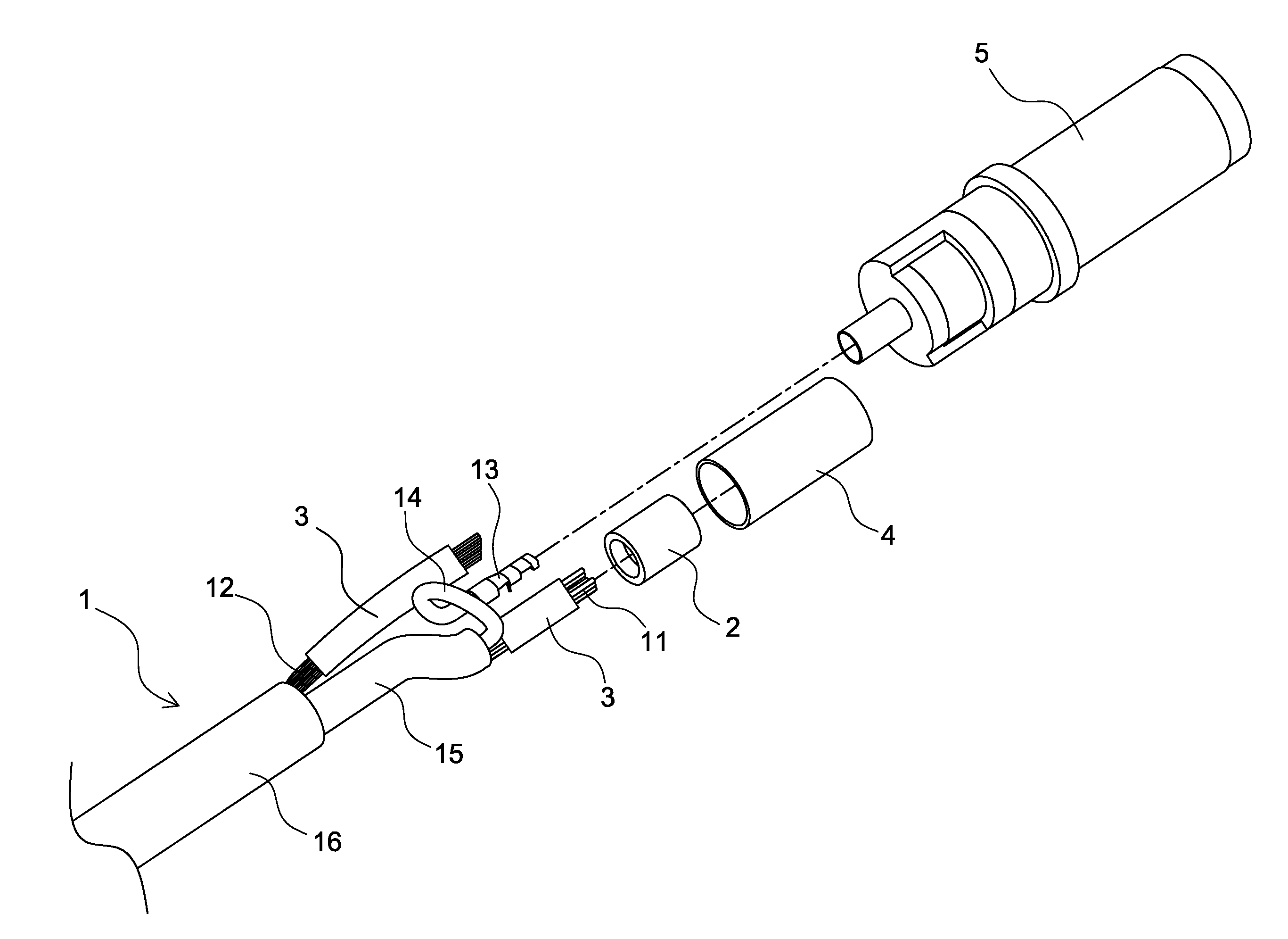
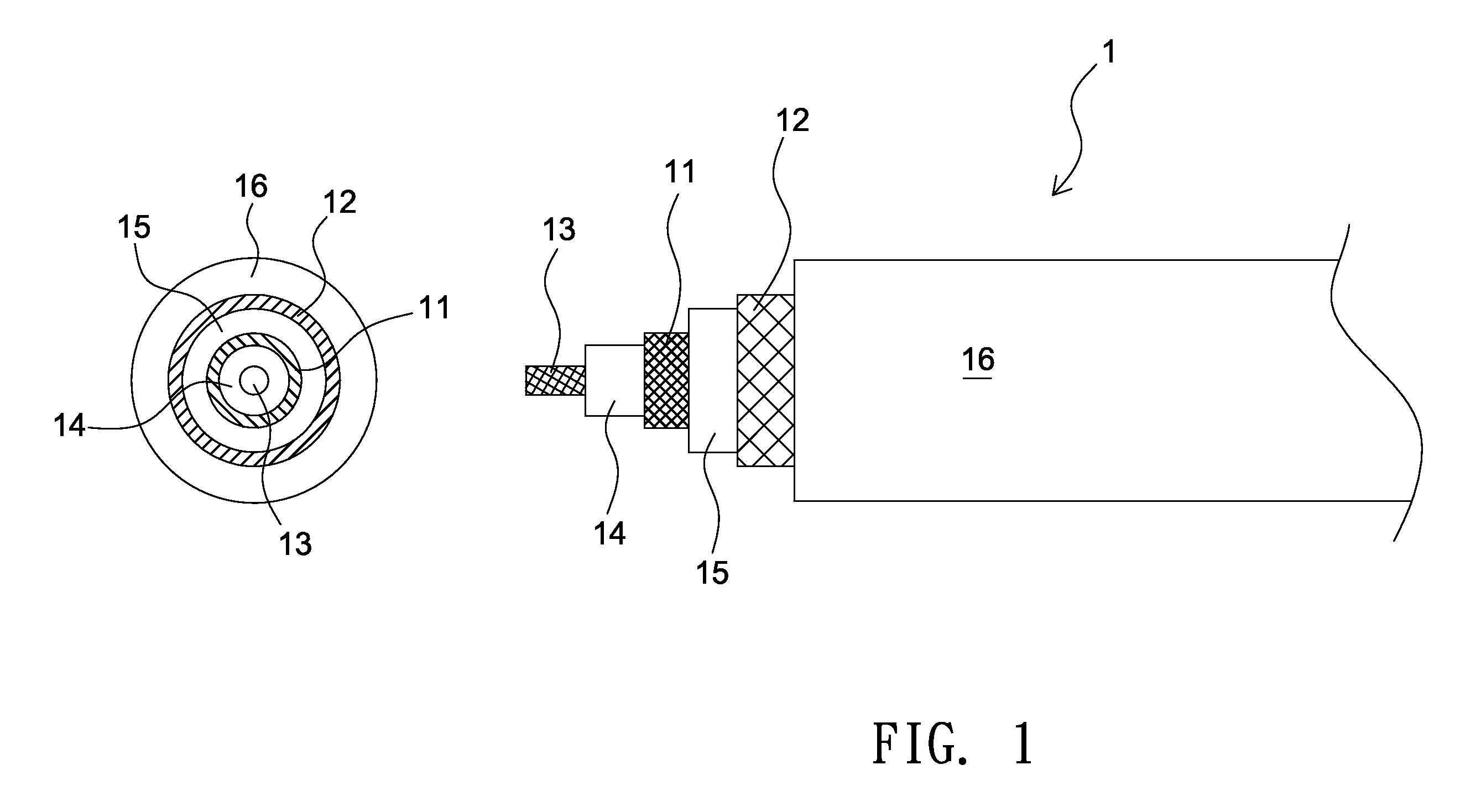
[0029]As shown in FIG. 1 and FIG. 2, the cable structure provided by the present invention is composed by a cable 1 and a positioning sleeve 2.

[0030]The cable 1 includes a first conductive wire 11 and a second conductive wire 12 respectively presenting anode and cathode electrodes; in practice the two conductive wires are metal interlacing wires with insulation layers, and the cable 1 is able to be further provided with a third conductive wire 13 according to actual needs, e.g. a signal wire, wherein the third conductive wire 13 is covered by a third insulation layer 14 so that the cable 1 is provided with functions of transferring positive and negative electricity and signals. As shown in FIG. 1, during the processing formation period of the cable 1, the first conductive wire 11 is installed on top of the third insulation layer 14 of the third conductive wire 13, then the first conductive wire 11 is covered by a second insulation layer 15, the second conductive wire 12 is installed...


PUM

PropertyMeasurementUnit
conductiveaaaaaaaaaa
cable structureaaaaaaaaaa
diametersaaaaaaaaaa

Abstract

The present invention relates to a cable structure, comprises a cable having a first, a second and a third conductive wires made of metal wire material, the third conductive wire is covered by a third insulation layer, the first conductive wire is interlaced on the third insulation layer and is covered by a second insulation layer, the second conductive wire is interlaced on the second insulation layer and is covered by a first insulation layer; the second conductive wire and the second insulation layer are exposed at one end of the first insulation layer, and the first conductive wire and the third conductive wire covered by the third insulation layer are exposed out of the second insulation layer; and a positioning sleeve passes through the first conductive wire and the third conductive wire having the third insulation layer and is sleeved and riveted on the second insulation layer so that the positioning sleeve is clamped and fastened on the second insulation layer and is served to abut against a cut portion of the first insulation layer for preventing the second insulation layer from retreating into the first insulation layer so short circuit of the first and the second conductive wires is effectively avoided.

Description

BACKGROUND OF THE INVENTION[0001]1. Field of the Invention[0002]The present invention relates to a cable structure, more particularly to a cable structure capable of preventing a second insulation layer from retreating into a first insulation layer.[0003]2. Description of Related Art[0004]A power cable is commonly seen in daily lives, for example being served to connect a round-column type power supply plug, and according to different diameters of power sockets of various electronic good, e.g. a notebook computer or mobile phone, the power supply plug may have different outer diameters. Or one end of the power cable is designed to be a strain relief (SR) of an electronic goods, e.g. a power adapter.[0005]In view of the whole structure of the mentioned cable, the cable includes a metal anode conduction wire, a metal cathode conduction wire and a signal wire, wherein the metal anode and cathode conduction wires are metal interlacing wires without insulation layers, and the signal wire...

Claims


Application Information

Patent Timeline
Patent Type & Authority Patents(United States)
IPC IPC(8): H01B7/18H01B9/02
CPCH01R43/28H01R13/5808H01R13/5845
Inventor CHANG, HSING-WANG
Owner TAIWAN LINE TEK ELECTRONICS
Why Eureka
Try Eureka