Imaging device with contrast AF, and control method for imaging device with contrast AF

a control method and imaging device technology, applied in the field of imaging devices, can solve the problem of no longer being able to use an af (auto focus) mechanism, and achieve the effect of small time lag and high precision

Active Publication Date: 2013-03-26
OM DIGITAL SOLUTIONS CORP
View PDF19 Cites 5 Cited by
  • Summary
  • Abstract
  • Description
  • Claims
  • Application Information

AI Technical Summary

Benefits of technology

[0008]The present invention has as its object to provide an imaging device that can perform focusing with a small time lag and with high precision in the case of imaging from a live view display function, and a control method for an imaging device.

Problems solved by technology

However, in a digital single lens reflex camera, in order to carry out live view display a movable mirror that is arranged in the imaging optical path is temporarily retracted, which means that during live view it is no longer possible to use an AF (Auto Focus) mechanism that employs a conventional phase difference method where an amount of defocus of the photographing lens is detected using subject light flux that has been reflected by a sub-mirror attached to the moveable mirror.

Method used


Image

  • Imaging device with contrast AF, and control method for imaging device with contrast AF
  • Imaging device with contrast AF, and control method for imaging device with contrast AF
  • Imaging device with contrast AF, and control method for imaging device with contrast AF

Examples


first embodiment

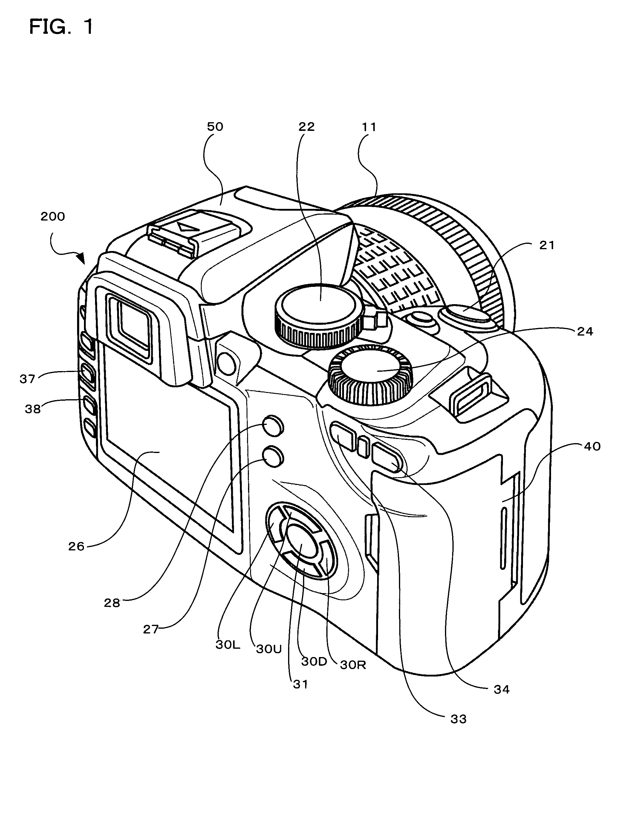
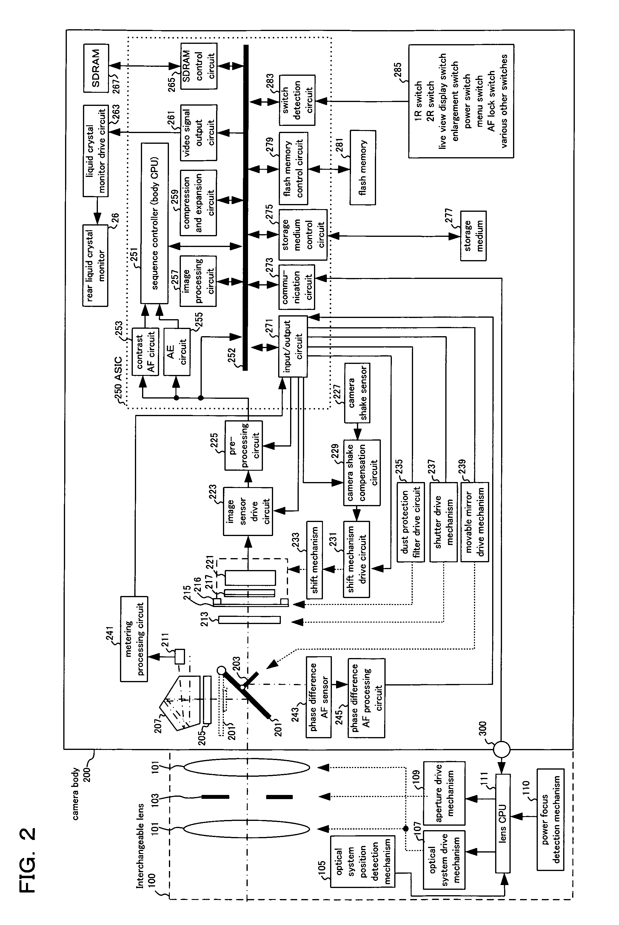
[0034]In the following, preferred embodiments using a digital single lens reflex adopting the present invention will be described using the drawings. FIG. 1 is an external perspective drawing of a digital single lens reflex camera relating to the present invention seen from a rear surface.

[0035]A release button 21, exposure mode dial 22, information setting dial 24 and strobe 50 etc. are arranged on the upper surface of the camera body 200. The release button 21 has a first release switch that turns on if the photographer presses the button down halfway, and a second release switch that is turned on when the button is pressed down fully. By turning this first release switch (hereafter called 1R) on (photographing preparation operation), the camera carries out exposure preparation operations such as focal point detection, focusing of the photographing lens, and light measurements for the subject brightness, and by turning the second switch (hereafter called 2R) on (photographing oper...

second embodiment

[0158]As described above, in the present invention, if continuous AF mode is set in the menu setting operation (#35), then at the time of starting a live view display operation (#51), with a state where the release button 21 has not been pressed down halfway (#53→No), each time a specified time (first time interval) has been reached by the timer (#57→Yes) a focus adjustment operation using contrast AF control is executed (#61), and if the release button 21 is pressed down halfway (#53→Yes) focus adjustment using contrast AF is executed continuously at an interval that is shorter than the specified time (second time interval) (#105). This second time interval can be measured using a timer, but with this embodiment a focus adjustment operation is carried out continuously without any particular timer operation.

[0159]Therefore, in the second embodiment of the present invention if continuous AF mode has been set the continuous AF control is carried out at a specified time interval determ...

third embodiment

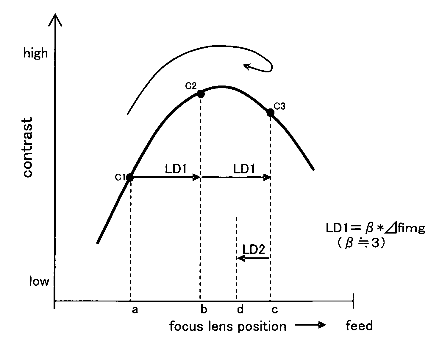
[0200]As has been described above, with the present invention, when continuous AF mode has been set, if a live view display operation is commenced (#51) the contrast AF control is repeatedly executed (refer to #61 in FIG. 4). Even if an operation to press down the release button 21 halfway is performed, the contrast AF control is repeatedly executed using continuous AF mode (refer to #105 in FIG. 19) and at this time the focus precision is switched (#205 and #106 in FIG. 20). In this manner, by switching focusing precision before and after pressing the release button 21 down halfway, when shooting in the live preview display state time lag is reduced, and it becomes possible to carry out high precision focus adjustment.

[0201]Also, in the third embodiment of the present invention, there are a first contrast AF mode where the photographing optical system 101 is guided to within a first permissible focus range, and a second contrast AF mode where the photographing optical system 101 is...


PUM


Abstract

According to the present invention, there is provided an imaging device, comprising: an imaging unit for receiving subject light flux, that has been made incident by the photographing lens, on an imaging surface, and photoelectrically converting a formed subject image to output image data; a display unit for carrying out a live view display operation using image data acquired by the imaging unit; a first contrast AF unit for obtaining contrast information of the subject information from image data acquired by the imaging unit and guiding the photographing lens into a first in-focus permissible range based on the contrast information, and a control unit for, when the live view display operation has started, executing a focus adjustment operation using the first contrast AF unit at a first time interval.

Description

[0001]Benefit is claimed, under 35 U.S.C. §119, to the filing date of prior Japanese Patent Application Nos. 2007-252354 filed on Sep. 27, 2007, 2007-252355 filed on Sep. 27, 2007, and 2007-252356 filed on September 27. These applications are expressly incorporated herein by reference. The scope of the present invention is not limited to any requirements of the specific embodiments described in the applications.BACKGROUND OF THE INVENTION[0002]1. Field of the Invention[0003]The present invention relates to an imaging device having a live view display function, and to a control method for the imaging device, and in detail relates to an imaging device, having a so-called live view display function (also called an electronic viewfinder function) for displaying an image acquired by an image sensor on a display unit, capable of focusing a photographing lens using an image signal during this live view display, and to a control method for an imaging device.[0004]2. Description of the Relat...

Claims


Application Information

Patent Timeline
Patent Type & Authority Patents(United States)
IPC IPC(8): H04N5/232H04N5/228
CPCH04N5/23293G03B13/32H04N23/52H04N23/663H04N23/67H04N23/672H04N23/673H04N23/651H04N23/667H04N23/631
Inventor KUNISHIGE, KEIJIMIYAZAKI, SATOSHI
Owner OM DIGITAL SOLUTIONS CORP
Why Eureka
Try Eureka