

Pressure balance valve
a technology of pressure balance valve and balance valve, which is applied in the direction of temperatue control, process and machine control, instruments, etc., can solve problems such as inability to maintain water temperatur
- Summary
- Abstract
- Description
- Claims
- Application Information
AI Technical Summary
Benefits of technology
Problems solved by technology
Method used
Image

Examples
Embodiment Construction
[0032]The present invention will be clearer from the following description when viewed together with the accompanying drawings, which show, for purpose of illustrations only, the preferred embodiment in accordance with the present invention.
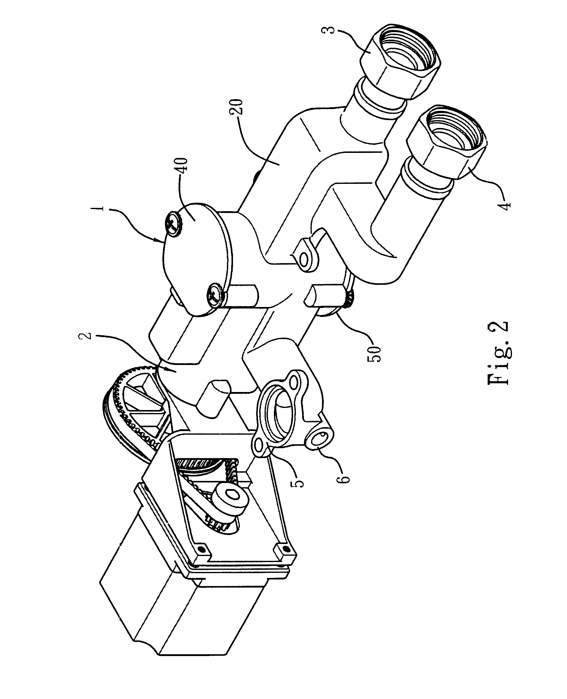
[0033]With reference to FIGS. 2-4, a pressure balance valve 1 according to a preferred embodiment of the present invention is installed on a showering equipment with a temperature controlling function, such as an inlet end of a temperature controlling valve 2; after cold and hot waters flow into the pressure balance valve 1 from a water feeding pipe via a first connector 3 to flow the cold water and via a second connector 4 to flow the hot water so that a water pressure is balanced, they are further fed into the temperature controlling valve 2 to be mixed together, and a mixed water is further fed into a specific watering device (such as a faucet or a spray shower head) from a selective first watering connector 5 or a selective second watering co...
PUM
 Abstract
Description
Claims
Application Information