Ultrathin cross-roller bearing

a cross-roller bearing, ultra-thin technology, applied in the direction of bearings, shafts and bearings, rotary bearings, etc., can solve the problems of inability to adjust, no retainer or separator for space balls, practical problems in downsizing or reducing, etc., to achieve smooth rolling, easy to make outer surfaces, and slender in diameter

Active Publication Date: 2013-04-02
NIPPON THOMPSON
View PDF14 Cites 7 Cited by
  • Summary
  • Abstract
  • Description
  • Claims
  • Application Information

AI Technical Summary

Benefits of technology

[0008]The present invention has as its principal object to overcome the challenges stated earlier and, in particular, to provide a cross-roller bearing in which the rolling element is a miniature roller having a diameter of 2 mm while a separator is interposed between any two adjoining rollers and correspondingly, inner and outer rings have ultrathin construction in conformity with the miniature roller, and further the roller together with the separator is introduced with ease into a circular track or load race defined between raceway surfaces of the inner and outer rings, the separator lying between any two adjoining rollers having a configuration of right cylinder that is most adequate to keep certainly the roller at desired position to run with smoothness throughout the circular race.
[0015]With the ultrathin cross-roller bearing in which the outer and inner rings are each made into one-piece construction as stated earlier, it is easier to make the outer and inner rings more compact and ultrathin in thickness and, correspondingly, the roller more slender in diameter may be used to get the cross-roller bearing as a whole lightweight and miniature in size. The less in size and weight the cross-roller bearing, the less the inertial mass in the swiveling and / or rocking components in which the ultrathin cross-roller bearing is used of machines such as industrial robots, optical instruments, medical appliances, machine tools, and so on. If that happens, the machines can respond to movement much faster. In addition to the outer and inner rings downsized as stated earlier, the separator to be interposed between the adjoining rollers has a configuration of right cylinder effective in keeping the roller against toppling or wobbling in posture. Especially, the right cylinder has axially opposite circular edges where axially opposite ends meet a circular side surface at right angles, instead of chamfered, to help keep positively the rollers in their proper posture while rolling through the race between the outer and inner rings, thereby permitting the rollers to bear various loads while rolling with smoothness. The circular recesses made on the axially opposite end of the separator make certain of better sliding contact with the rollers irrespective of working orientation or posture of the bearing including a tilted posture, another posture lying on its side, and so on. Moreover, the recesses on the axially opposite end of the separator keep a reserve of lubricant to ensure positive and better lubrication of the rollers, contributing to antifriction bearing operation.

Problems solved by technology

Moreover, there is no retainer or separator to space balls that fit for rolling movement into the annular raceway defined between the inner and outer rings.
With the prior cross-roller bearing with plug recited above, nevertheless, there is a practical issue in downsizing or reduction as the inner and outer rings both made thicker in size.
Next, the thin rolling-contact bearing constructed as stated earlier, although most convenient for simple usage as the rolling elements are balls, is unfit for revolution with high turning accuracy and also insufficient for smooth turning performance with permitting different loads or composite loads.

Method used


Image

  • Ultrathin cross-roller bearing
  • Ultrathin cross-roller bearing
  • Ultrathin cross-roller bearing

Examples


Embodiment Construction

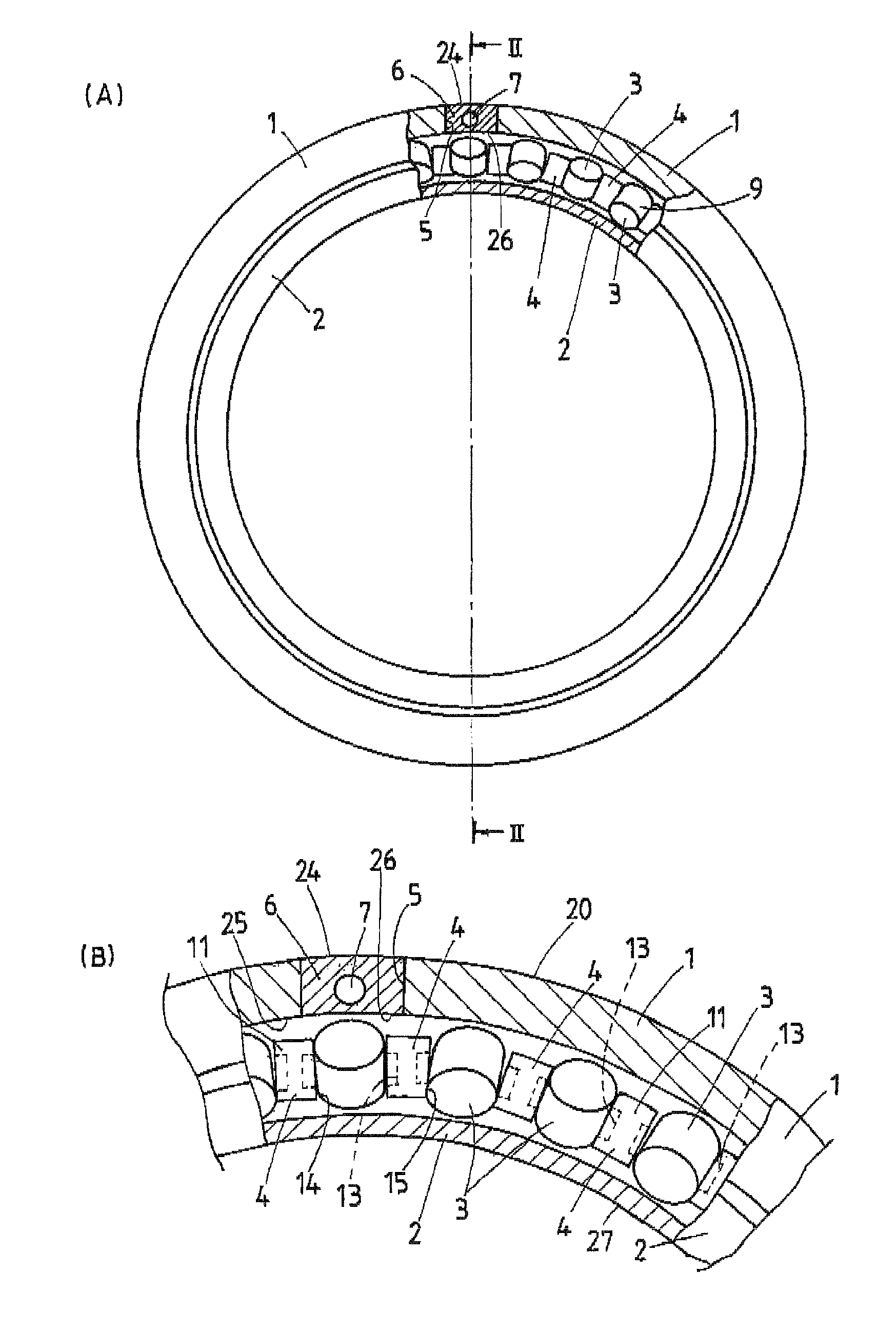
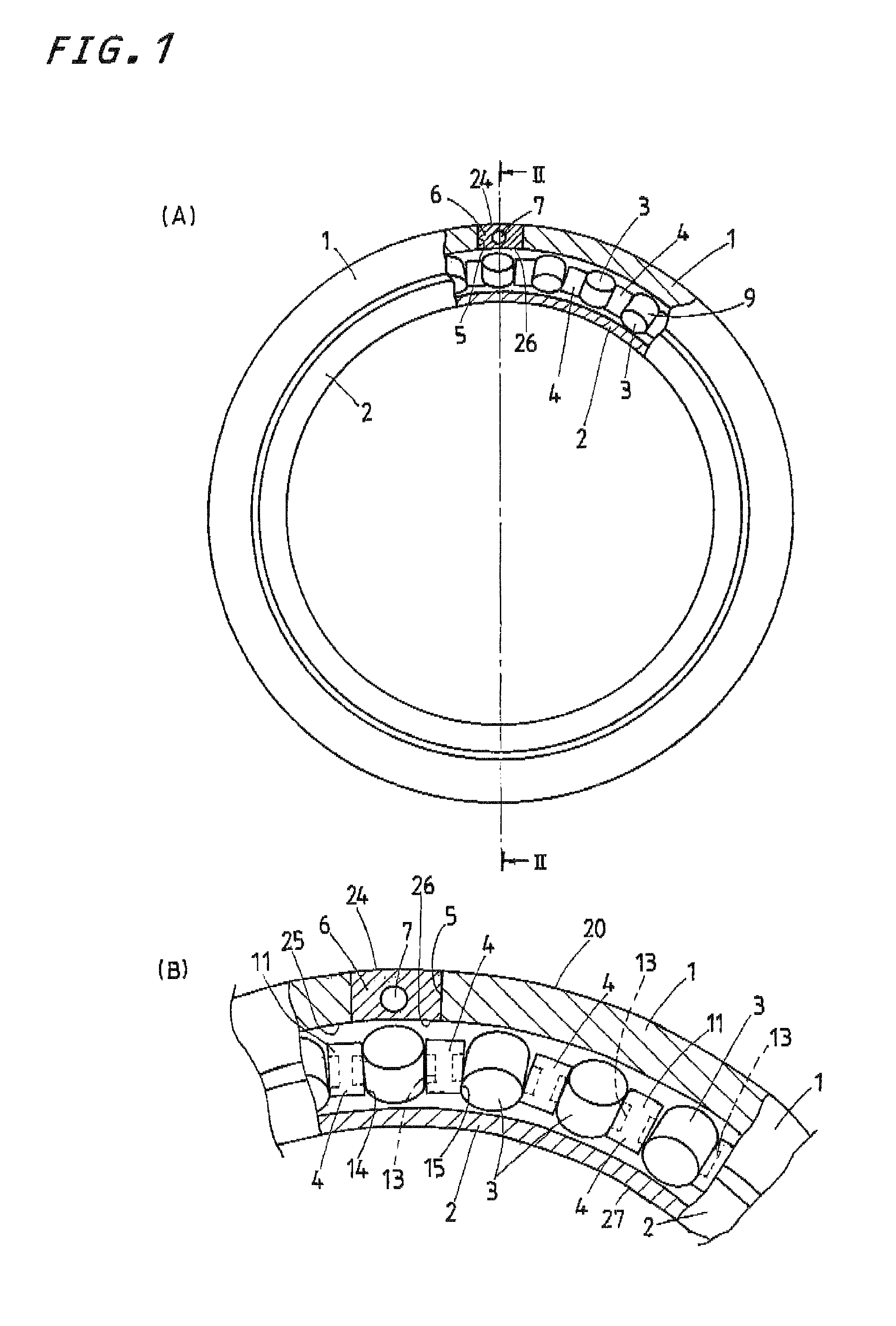
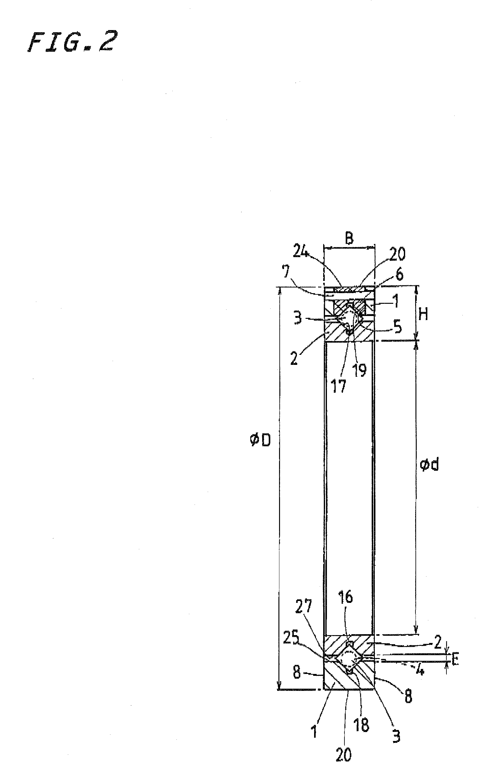
[0023]The ultrathin cross-roller bearing according to the present invention is the most lightweight and more compact or downsized in construction than ever to find extensive applications in relative sliding, rocking and turning systems used in a diversity of machinery including industrial robots, optical instruments, medical appliances, machine tools, various assembling machines, semiconductor fabricating equipment, measurement equipments and so on, which requires slim construction, high stiffness and turning accuracy of the bearings. With the ultrathin cross-roller bearing of the present invention, especially, the inner and outer rings whose width and thickness are slim or thin are each made in one-piece construction while the inside diameter of the bearing is set in a range of 20˜50 mm. The cross-roller bearing constructed according to the present invention is envisages having better response even with most lightweight.

[0024]A preferred first embodiment of the ultrathin cross-roll...


PUM


Abstract

An ultrathin cross-roller bearing composed of outer and inner rings, more than one roller rolling through between the outer and inner rings, and a separator interposed between any two adjoining rollers. With the ultrathin cross-roller bearing constructed as stated earlier, the separator lying between the adjoining rollers is in the form of right cylinder better for keeping constantly the roller in proper posture, getting the bearing itself downsized and lightweight as small as possible, and further making sure of positive lubrication. The outer and inner rings are each made into one-piece construction. The inner ring has an inside diameter in a range of from 20 mm to 50 mm. The roller used in the ultrathin cross-roller bearing has a diameter of 2 mm to render a transverse section given by a product of a radial height and a bearing width in transverse section small or ultrathin in thickness.

Description

FIELD OF THE INVENTION[0001]The present invention relates generally to a cross-roller bearing having outer and inner rings and more than one rolling element or cylindrical roller whose axis is tilted alternately in opposite direction to each other and, more particularly, a cross-roller bearing with more than one roller which gets minimized in diameter to render overall the roller bearing ultrathin in thickness as well as ultralight in weight.BACKGROUND OF THE INVENTION[0002]Roller bearings of the type called cross-roller bearing because the rollers are arranged in circular direction in a fashion any the adjacent rollers are alternately tilt in opposite direction to each other in recent years have been increasingly incorporated in swiveling and / or rocking components of a variety of machinery including industrial robots, machine tools, medical appliances, optical instruments, and so on. Thus, various cross-roller bearings different in style, construction and size have been developed c...

Claims


Application Information

Patent Timeline
Patent Type & Authority Patents(United States)
IPC IPC(8): F16C19/50F16C19/40
CPCF16C19/362F16C33/37F16C2240/40F16C33/34F16C33/58F16C2240/46F16C2240/60F16C2240/70
Inventor KUNIMOTO, KAZUMASAYOSHIDA, YOSHIHIRO
Owner NIPPON THOMPSON
Why Eureka
Try Eureka