Supply device, and method for supplying band-like member

a band-like member and supply device technology, applied in metal-working feeding devices, manufacturing tools, mechanical devices, etc., can solve the problems of strip-shaped members being fully stretched and broken in the end, deteriorating process efficiency, and helical diameter and helical pitch reductions, etc., to achieve the effect of simple structur

Inactive Publication Date: 2016-03-01
SEKISUI CHEM CO LTD
View PDF14 Cites 0 Cited by
  • Summary
  • Abstract
  • Description
  • Claims
  • Application Information

AI Technical Summary

Benefits of technology

[0032]In the feeding device of the present invention, the feeding motor is installed to the support frame. The feeding rollers are rotated together with the rotary frame being rotated, while being rotated about respective axes thereof, so that it becomes possible to feed out the strip-shaped member in the form of an adequate helical configuration, with a significantly simple structure. Further, the strip-shaped member feeding method of the present invention makes it possible to install the feeding device and feed out the strip-shaped member in the form of an adequate helical configuration, irrespective of before initiation of a process or during the process. Thus, it becomes possible to eliminate a need for deploying a worker for the purpose of feeding the strip-shaped member to the pipe forming device, thereby performing a pipe forming process automatically, smoothly and efficiently.

Problems solved by technology

If the feeding of the strip-shaped member is insufficient, the strip-shaped member before reaching the pipe forming device is gradually reduced in helical diameter and increased in helical pitch, which is likely to cause a situation where the strip-shaped member is fully stretched and broken in the end.
This gives rise to a need to return the strip-shaped member to its original desirable helical configuration, resulting in deterioration in process efficiency.
However, deployment of many workers leads to an increase in cost.
Moreover, tasks inside an existing pipe involve a risk of unexpected events.

Method used


Image

  • Supply device, and method for supplying band-like member
  • Supply device, and method for supplying band-like member
  • Supply device, and method for supplying band-like member

Examples


Embodiment Construction

[0048]With reference to the drawings, a feeding device and a strip-shaped member feeding method, according to one embodiment of the present invention, will now be described.

[0049]FIGS. 1 to 5 illustrate a feeding device 10 according to one embodiment of the present invention, and FIG. 6 schematically illustrates a state of an underground pipeline during a pipe forming process.

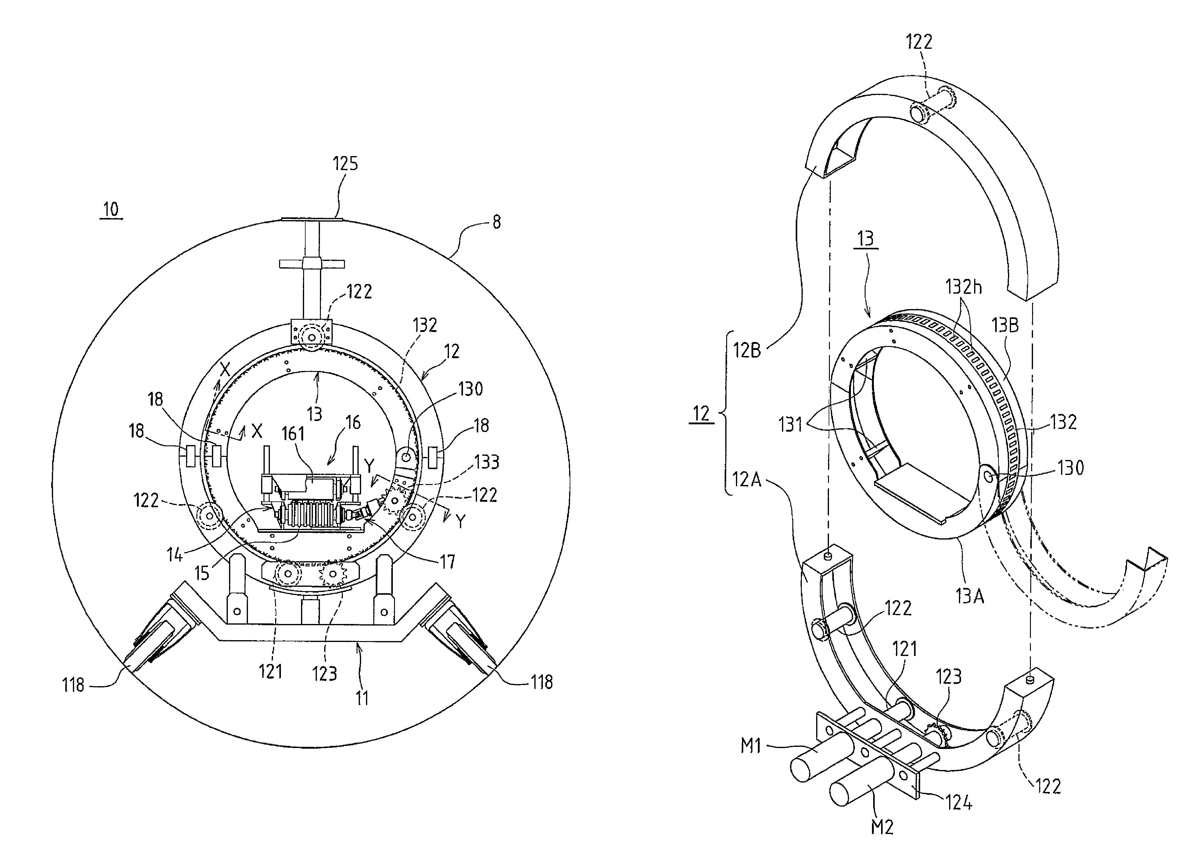
[0050]The feeding device 10 is designed to feed a strip-shaped member 100 toward an aftermentioned pipe forming device 1. The feeding device 10 comprises: a mount 11 equipped with a plurality of rotatable wheels 118; an annular-shaped support frame 12 fixed to the mount 11; an annular-shaped rotary frame 13 located on the side of an inner periphery of the support frame 12 and supported in a rotatable manner; paired feeding rollers 15, 161 rotatably supported with respect to the rotary frame 13 through a mounting bracket 14; and a guide trough 151 supported in the same manner as the feeding roller 15 and configu...


PUM

PropertyMeasurementUnit
central angleaaaaaaaaaa
rotationaaaaaaaaaa
driving forceaaaaaaaaaa

Abstract

A feeding device (10) comprises: a support frame (12); an annular-shaped rotary frame (13); paired feeding rollers (15, 161) for nipping a strip-shaped member therebetween; a rotating motor (M1) for rotating the rotating frame (13); a feeding motor (M2) for rotating at least one (15) of the feeding rollers; and a driving force transmission mechanism (17) comprising a rotatable member relatively rotatable with respect to the rotating frame (13). The rotating frame (13) is rotated by driving of the rotating motor (M1) through a roller or a gear, and the at least one feeding roller (15) is rotated by the feeding motor (M2) through the driving force transmission mechanism (17), so that the strip-shaped member (100) is fed out in the form of a given helical configuration.

Description

TECHNICAL FIELD[0001]The present invention relates to a feeding device for feeding a strip-shaped member to a pipe forming device, and a feeding method for feeding a strip-shaped member using the feeding device.BACKGROUND ART[0002]In regard to an aging existing pipe, there is a technique of, through the use of an elongated strip-shaped member, forming a pipe-like body inside the existing pipe by a pipe forming device, to rehabilitate the existing pipe based on the pipe-like body. In such a rehabilitation technique, a strip-shaped member overlappingly wound around a drum is fed to a pipe forming device installed inside an existing pipe. In this process, it is necessary to allow the strip-shaped member pullingly unwound from the drum to be fed toward the pipe forming device while being formed in a given helical configuration. This means that the strip-shaped member has to be fed in synchronization with orbital and forward speeds of the pipe forming device. If the feeding of the strip-...

Claims


Application Information

Patent Timeline
Patent Type & Authority Patents(United States)
IPC IPC(8): B21D43/00B21C37/12B29C53/56B21D3/00F16L55/165B29C63/32B29C53/78
CPCB21D43/006B21C37/121B21C37/126B21D3/00B29C53/566B29C63/32F16L55/1655B29C53/78
Inventor TSUDA, JUNYAMANE, TOSHIOYAMAJI, TOMONORI
Owner SEKISUI CHEM CO LTD
Why Eureka
Try Eureka