Self-Locking Belt Retractor With Deactivation of its Belt Webbing-Sensitive Control System Operating in the Retracting Direction of the Belt Shaft

a belt webbing and control system technology, applied in the direction of belt retractors, vehicle safety belts, vehicle components, etc., can solve the problems of disadvantageous control methods and undesirable rattle noise generation, and achieve the effect of reducing thickness, reducing noise, and reducing nois

Active Publication Date: 2015-01-01
AUTOLIV DEV AB
View PDF15 Cites 0 Cited by
  • Summary
  • Abstract
  • Description
  • Claims
  • Application Information

AI Technical Summary

Benefits of technology

[0007]A feature of the invention provides that both legs of the control clip enclose the actuator between them and the actuator configures contact surfaces for the clip legs for taking along the clip during the rotation of the control plate in the belt retracting direction as well as the belt extending direction. One of the two clip legs projects during rotation of the control plate in the belt retracting direction into the pivoting path of a pivot arm of the inertial mass located opposite to the blocking arm in the case of a release and prevents a pivoting out of the inertial mass in this blocking position of the torsion spring and releases the inertial mass with a rotation of the control plate in the belt extending direction as a result of a relative rotation of the torsion spring with respect to the control plate in a release position of the control clip.
[0008]The invention is thus based on the basic principle of restricting the inertial mass from pivoting out independently from the inertial torque acting thereon by means of the provided control clip. Since an activation of the inertial mass with its pivoting must be possible without hindrance in particular during the belt webbing extension, it should be ensured by means of the special configuration and arrangement of the control clip in connection with the actuator that the control plate, which rotates together with the belt shaft with an incipient belt webbing extension, is first rotated by a specific angle of rotation relative to the control clip, which remains in place as a result of its frictionally engaging bearing, until the clip leg provided for fixing the inertial mass is located outside of the pivoting path of the inertial mass, so that the inertial mass can be freely pivoted out with corresponding rotating motions of the control plate. In this release position of the control clip, the clip leg comes to rest on the associated striking surface of the actuator and is taken along in this position during the further rotation of the control plate, so that the control clip retains its assumed release position on the control plate. With a subsequent rotation of the belt shaft with the control plate in the belt retracting direction occurs in turn a relative rotation of the control plate with respect to control clip, which is initially again stopped due to its frictionally engaged bearing, so that the inertial mass shifts outward with its pivot arm across the end of the appropriate clip leg with the rotation of the control plate, so that the clip leg can assume its function of fixing the inertial mass at the end of the retraction motion. In this again occupied blocking position of the control clip, the actuator abuts again with another contact surface against the other leg of the control clip, so that the control clip is respectively taken along in its blocking position with the rotation of the control plate and in this way retains its blocking position.
[0009]A contact surface for the clip leg provided for fixation of the inertial mass is configured on the pivot arm of the inertial mass according to an exemplary embodiment of the invention.
[0010]In order to ensure that the blocking position of the control clip is not only effective in an exact position of the appropriate leg with respect to the inertial mass, there is the provision according to an exemplary embodiment of the invention, that the clip leg provided for fixation of the inertial mass projects into the pivoting path by a predetermined angle of rotation transected by the inertial mass as a result of the relative rotation of the control plate bearing the inertial mass with respect to the fixed control clip and the contact surface configured on the inertial mass has an extension in peripheral direction that corresponds to the angle of rotation of the control plate established for fixation of the inertial mass. Since the object of the invention concerns the sudden stop of the rotating motion of the belt shaft at the end of its retraction motion, and thus a possible inertia-dependent further rotation of the control plate with respect to the belt shaft within the frame of the design of the coupling of the belt shaft and the control plate with respect to each other, the corresponding angle of rotation for fixation of the inertial mass against deflection by means of the clip leg needs only to correspond to this constructively fixed further rotation of the control plate.
[0007]A feature of the invention provides that both legs of the control clip enclose the actuator between them and the actuator configures contact surfaces for the clip legs for taking along the clip during the rotation of the control plate in the belt retracting direction as well as the belt extending direction. One of the two clip legs projects during rotation of the control plate in the belt retracting direction into the pivoting path of a pivot arm of the inertial mass located opposite to the blocking arm in the case of a release and prevents a pivoting out of the inertial mass in this blocking position of the torsion spring and releases the inertial mass with a rotation of the control plate in the belt extending direction as a result of a relative rotation of the torsion spring with respect to the control plate in a release position of the control clip.
[0012]It is sufficient for the configuration of the blocking function of the control clip according to an exemplary embodiment of the invention if the bent section of the clip leg provided for fixation of the inertial mass remains at a distance from the contact surface of the inertial mass with the inertial mass in rest position.
[0013]As an alternative it can be provided that the bent section of the clip leg provided for fixation of the inertial mass rests on the contact surface of the inertial mass when the inertial mass is in the rest position. This is connected herewith to the additional advantage that the associated leg of the control clip also prevents at the same time any rattling noises in its blocking position by means of a fixation of the inertial mass.
[0015]In an alternative embodiment of the invention it can be provided that the control clip is configured as a punched bent-part produced from a corresponding metal sheet. The control clip configured with a flat design is provided in this way with a reduced thickness but with the same strength when compared to a bent wire part and can basically be produced with a more accurate shape than the bent wire part.
[0016]In such an exemplary embodiment it can be provided that the end of the bent section of the clip leg provided for fixation of the inertial mass is configured in T-shape with attachments projecting laterally from the axis of the spring leg. A correspondingly good contact and guidance of the inertial mass, on the one hand, and the actuator, on the other hand, is realized in this way.
[0017]It can be provided herein that the bearing area of the control clip configured as a punched bent part is provided with a plastic coating, wherein the clip made of plastic and metal can be configured as one piece. The bearing area of the control clip can thereby also be optionally configured as a closed ring.

Problems solved by technology

In such a belt retractor provided with a belt-webbing-sensitive activation mechanism there can arise the problem, for example, when the belt shaft rotates with such rotational speed in the retracting direction after the seat belt is removed that the belt shaft springs back due to the inertia in the extending direction as a result of the stop of the rotating motion effective at the end of the belt webbing retraction.
Another problem occurs when the webbing-sensitive control system responds to small vibrations when the seatbelt is unlatched, giving rise to on it desirable rattle noise generation.
This can lead in a disadvantageous way to control problems in the interactions of the torsion spring with the inertial mass.

Method used


Image

  • Self-Locking Belt Retractor With Deactivation of its Belt Webbing-Sensitive Control System Operating in the Retracting Direction of the Belt Shaft
  • Self-Locking Belt Retractor With Deactivation of its Belt Webbing-Sensitive Control System Operating in the Retracting Direction of the Belt Shaft
  • Self-Locking Belt Retractor With Deactivation of its Belt Webbing-Sensitive Control System Operating in the Retracting Direction of the Belt Shaft

Examples


Embodiment Construction

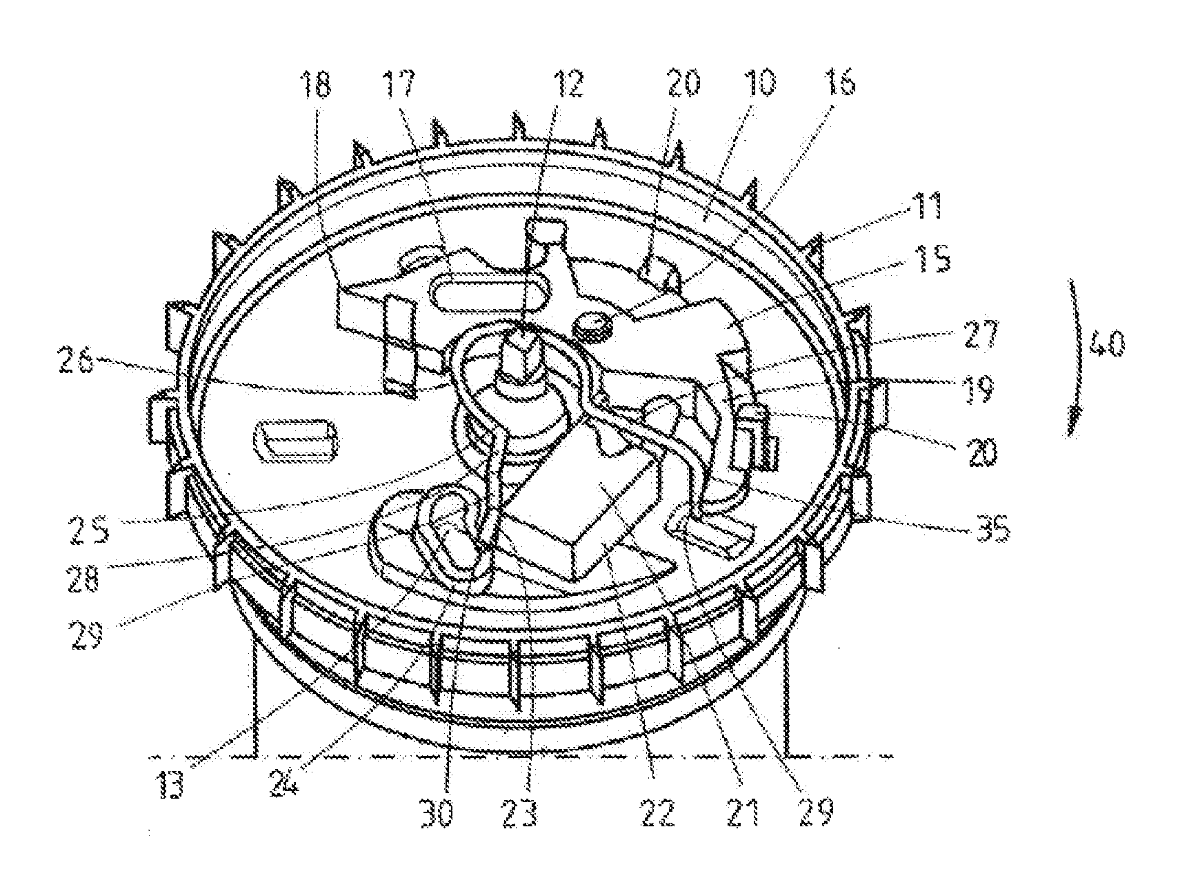
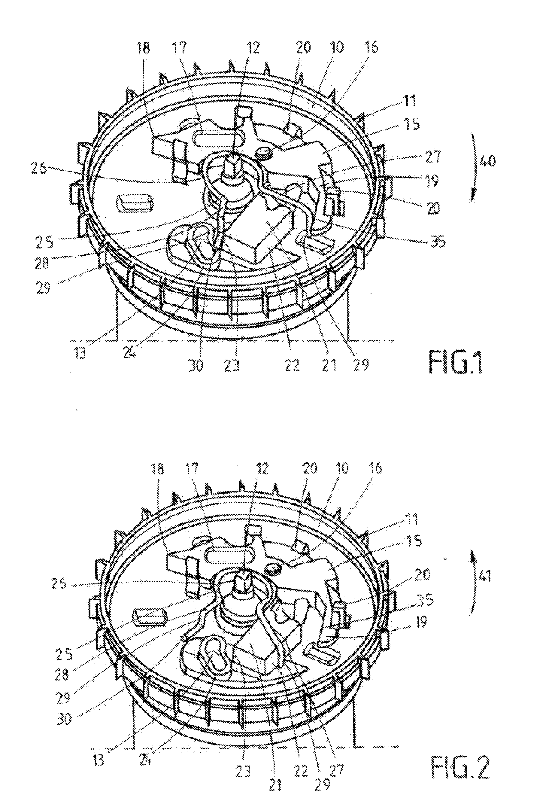
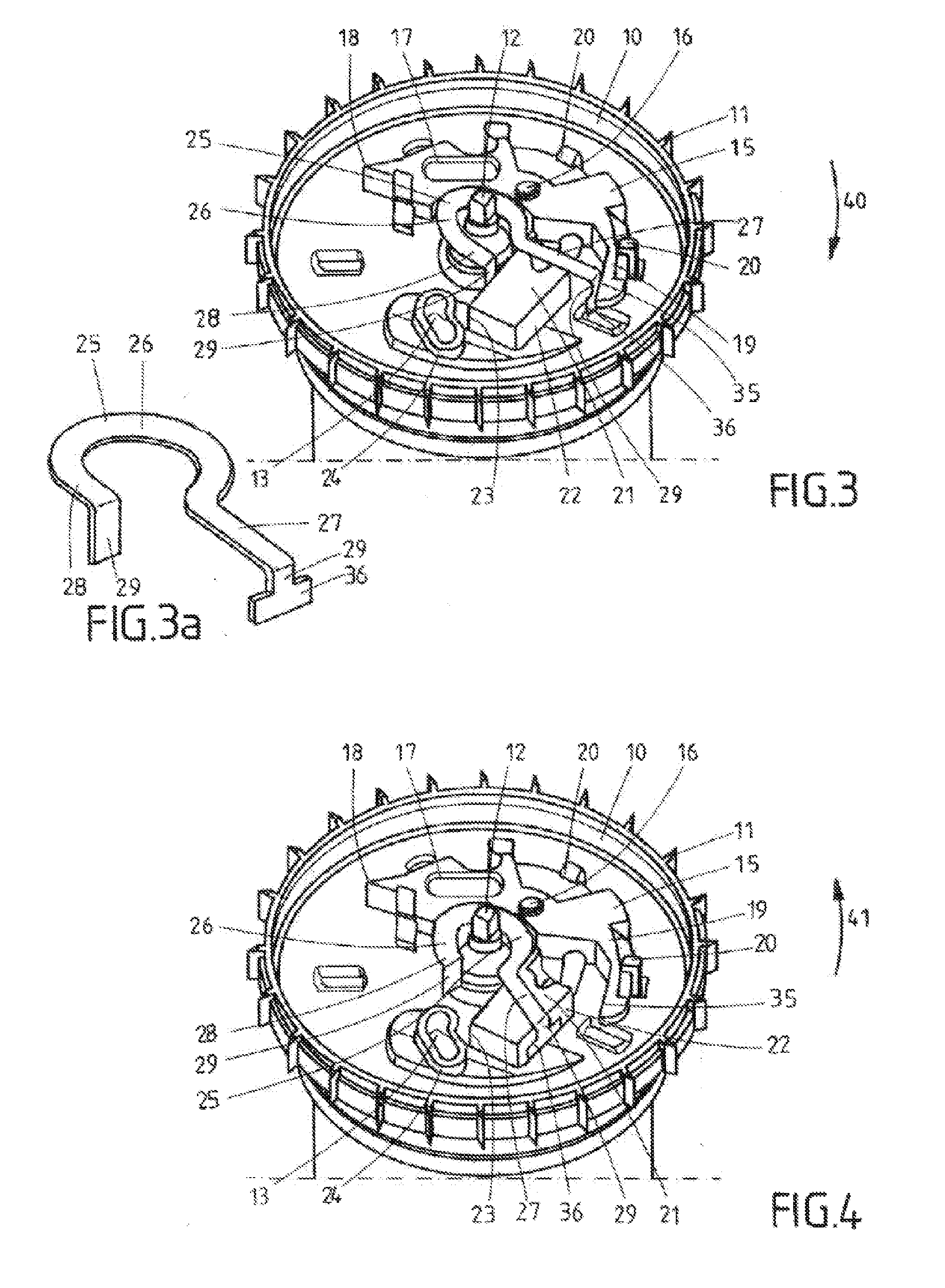
[0024]The control plate 10 that can be seen in FIG. 1 is rotatably mounted on a shaft extension 12 and has an outer gearing 11 for coacting with a vehicle-sensitive control system. A slot 13, in which a pivot 14 depicted merely in FIGS. 1 to 4 and arranged on the locking element mounted on the belt shaft (which is not shown in further detail) is configured in the control plate 10. A two-armed inertial mass 15 is furthermore pivotably mounted on the control plate 10 by means of a pivot bearing 16 configured in its central area, wherein the two-armed inertial mass has a blocking arm 17 with an outer blocking tip 18 and a pivot arm 19. The inertial mass 15 is held on the control plate 10 by holding arms 20 mounted on the control plate 10 and correspondingly angled, so that the inertial mass 15 is fixed thereon in particular with its mutual rotation with the control plate 10. As is well known in the prior art and not shown in further detail, the pot-shaped recess of the control plate 10...


PUM


Abstract

A self-locking belt retractor for seat belts having a belt shaft rotatably mounted in a housing frame and having a belt-webbing-sensitive actuation mechanism A control plate that can be deflected with a relative rotation between the belt shaft and the control plate The control plate bears a two-arm eccentrically mounted inertial mass A control clip is rotatably frictionally mounted on a bearing surface for the belt shaft. An actuator of the control plate engages two legs of control clip and forms contact surfaces for the legs for shifting the control plate in belt retracting direction as well as in belt extending direction. One of the legs projects during rotation of the control plate in the belt retracting direction into the pivoting path of a pivot arm of the inertial mass and releases the inertial mass with a rotation of the control plate in the belt extending direction.

Description

CROSS REFERENCE TO RELATED APPLICATIONS[0001]This application claims priority to German Patent Application No. 10 2011 057 066.7, filed Dec. 27, 2011 and PCT / EP2012 / 075958, filed Dec. 18, 2012.FIELD OF THE INVENTION[0002]The invention concerns a self-locking belt retractor for seat belts having a belt shaft rotatably mounted in a housing frame and pretensioned by means of a retraction spring in the retracting direction of the belt webbing and a belt-webbing-sensitive actuation mechanism, which has a control plate coupled to the belt shaft for deflecting a locking element arranged on the belt spool that can be deflected against spring action with a relative rotation between the belt shaft and the control plate until it engages with a housing gearing. The control plate bears a two-arm inertial mass, which is eccentrically pivotably mounted on the control plate and can be radially deflected against the action of a reset spring, and which, in case of release as a result of the angular a...

Claims


Application Information

Patent Timeline
Patent Type & Authority Applications(United States)
IPC IPC(8): B60R22/38
CPCB60R22/38
Inventor HEINE, VOLKMAR
Owner AUTOLIV DEV AB
Why Eureka
Try Eureka