Quadrupole mass spectrometer

a mass spectrometer and quadripole technology, applied in the direction of isotope separation, electric discharge tubes, separation processes, etc., can solve the problems of reducing temporal resolution, increase the mass width of the scan margin, and excessive and useless waiting time

Active Publication Date: 2013-04-02
SHIMADZU CORP
View PDF18 Cites 10 Cited by
  • Summary
  • Abstract
  • Description
  • Claims
  • Application Information

AI Technical Summary

Benefits of technology

[0026]In the quadrupole mass spectrometer according to the first aspect of the present invention, an excessive and useless waiting time that arises when the voltage applied to the quadrupole mass filter is changed among the adjacent cycles in a scan measurement, an SIM measurement, or an MRM measurement can be shortened. Therefore, for example, the cycle period of a mass scan can be shortened even for the same scan rate. This shortens what is called the dead time, i.e. a period of time when no mass analysis data can be obtained, thereby increasing the temporal resolution.
[0027]In the quadrupole mass spectrometer according to the second aspect of the present invention, the mass width of the scan margin for stabilizing a measurement which is set outside the mass range in a scan measurement can be decreased. Therefore, in the case where, for example, the scan rate is low or the mass range is located in a relatively low region, the cycle period of the mass scan can be shortened. This shortens what is called the dead time, i.e. a period of time when no mass analysis data can be obtained, thereby increasing the temporal resolution.

Problems solved by technology

Since such a rapid change in the voltage inevitably causes an overshoot (undershoot), a waiting time (settling time) is needed for allowing the voltage to stabilize after the change.
Therefore, the longer the settling time is, the longer the time interval is between the mass scans, i.e. the longer the cycle of the mass scan is, which decreases the temporal resolution.

Method used


Image

  • Quadrupole mass spectrometer
  • Quadrupole mass spectrometer
  • Quadrupole mass spectrometer

Examples


Embodiment Construction

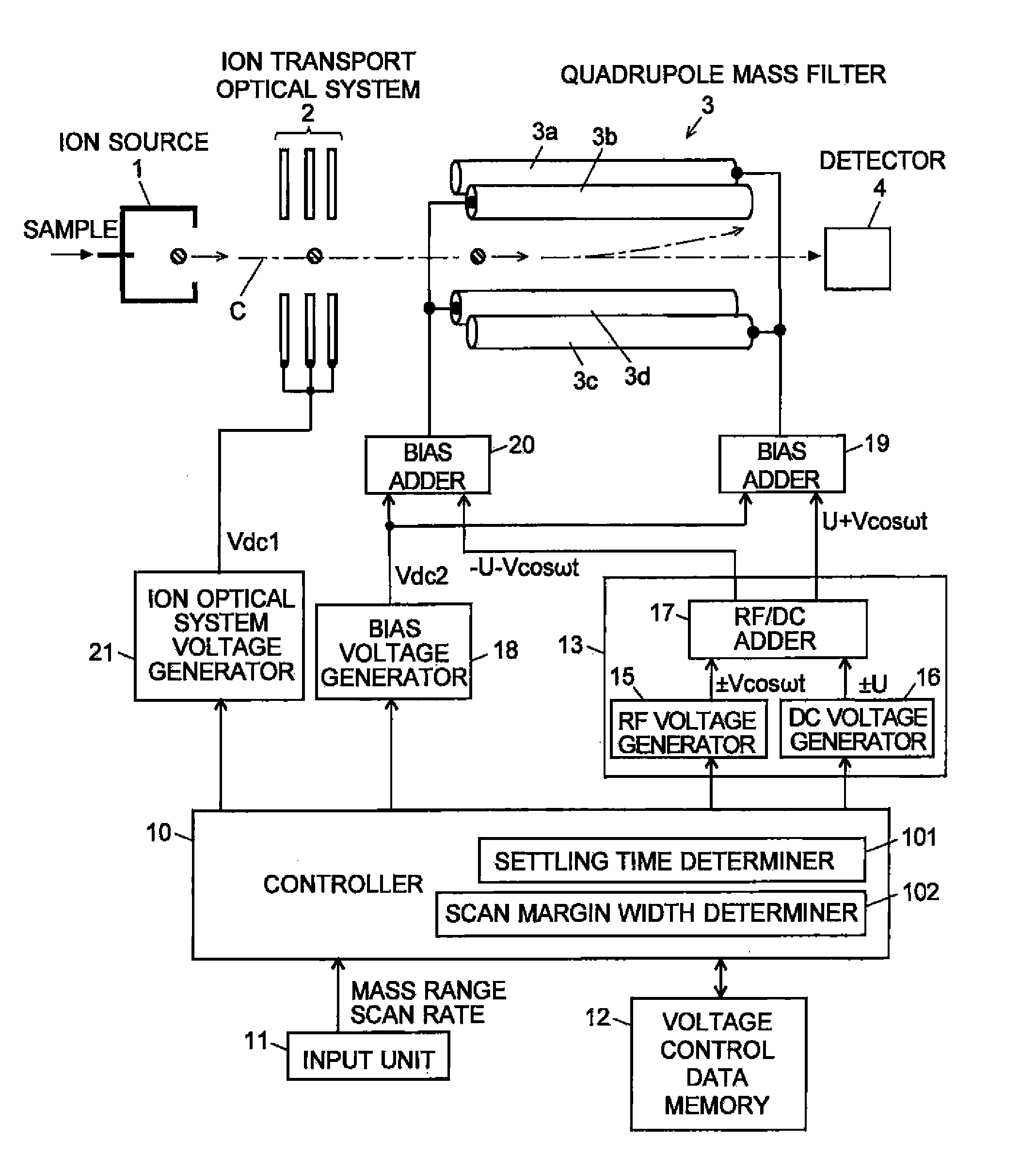
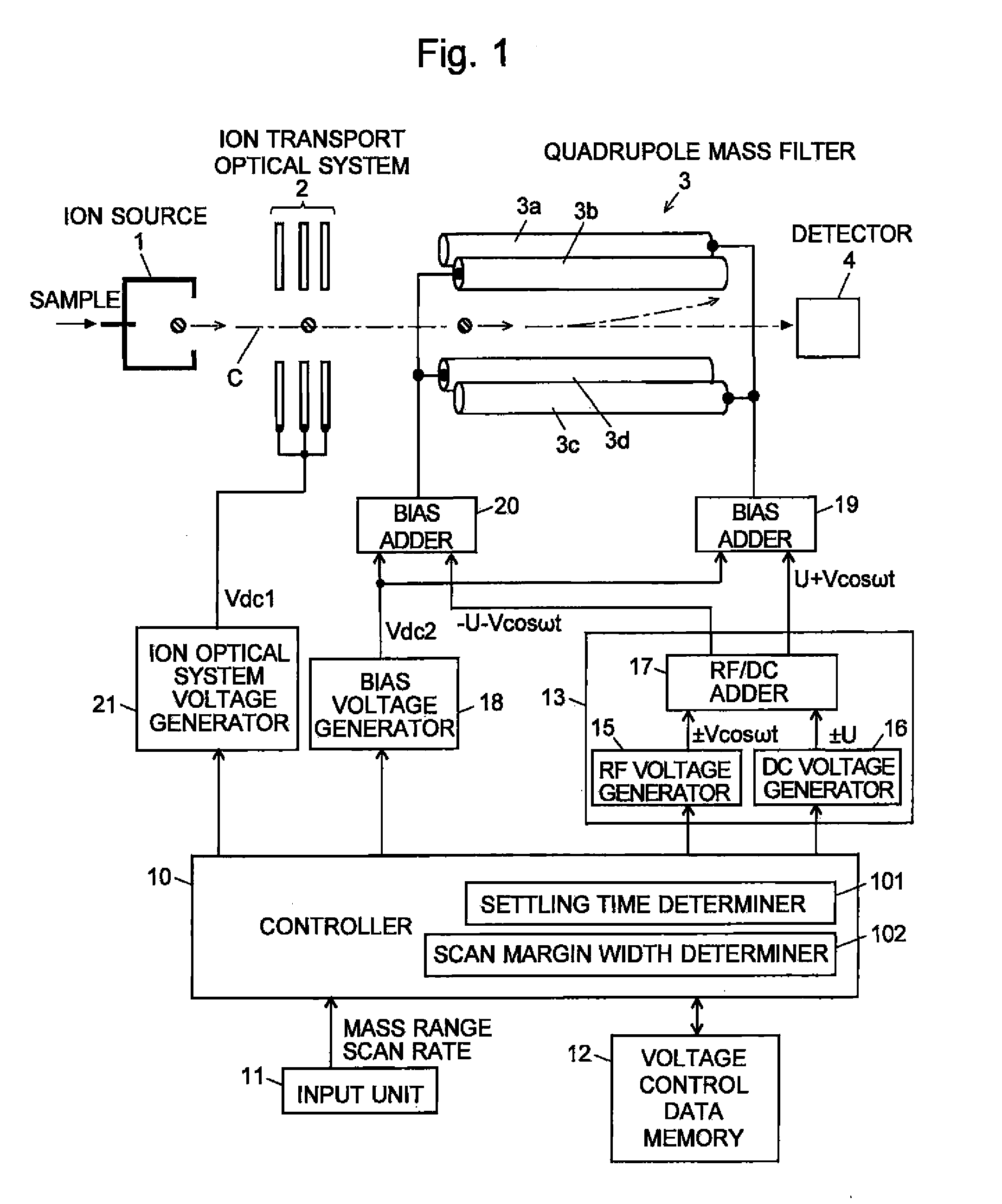
[0052]A quadrupole mass spectrometer of an embodiment of the present invention will be described with reference to the attached figures. FIG. 1 is a configuration diagram of the main portion of the quadrupole mass spectrometer according to this embodiment. The same components as in FIG. 6 which have been already described are indicated with the same numerals. In the quadrupole mass spectrometer according to this embodiment, a gaseous sample is injected into the ion source 1, and a gas chromatograph can be connected in the previous stage of the mass spectrometer. A liquid sample may also be analyzed by using an atmospheric pressure ion source (such as an electrospray ion source) as the ion source 1, and maintaining this ion source 1 at an atmosphere of approximate atmospheric pressure while placing the quadrupole mass filter 3 and the detector 4 in a high vacuum atmosphere by a multistage differential pumping system. In such a case, a liquid chromatograph can be connected in the prev...


PUM


Abstract

In a scan measurement in which a mass scan is repeated across a predetermined mass range, when a voltage is returned from a termination voltage of one scan to an initiation voltage for the next scan, an undershoot or other drawbacks occur to destabilize the voltage value. Therefore, an appropriate waiting time is required. Conventionally, this waiting time has been set to be constant regardless of the analysis conditions. On the other hand, in the quadrupole mass spectrometer according to the present invention, the mass difference ΔM between the scan termination mass and the scan initiation mass is computed based on the specified mass range, and a different settling time is set in accordance with this mass difference. When the mass difference ΔM is small and hence requires only a short voltage stabilization time, a relatively short settling time is set. This shortens the cycle period of the mass scan, which increases the temporal resolution.

Description

CROSS-REFERENCE TO THE RELATED APPLICATIONS[0001]This application is a divisional of application Ser. No. 12 / 994,019, filed on Nov. 22, 2010, which is a national stage of international application No. PCT / JP2008 / 001307, filed on May 26, 2008, the entire contents of which are incorporated herein by reference.TECHNICAL FIELD[0002]The present invention relates to a quadrupole mass spectrometer using a quadrupole mass filter as a mass separator for separating ions in accordance with their mass (or m / z, to be exact).BACKGROUND ART[0003]A quadrupole mass spectrometer using a quadrupole mass filter in a mass separator for separating ions in accordance with their mass-to-charge ratio has been known as a type of mass spectrometer. FIG. 6 is a schematic configuration diagram of a general quadrupole mass spectrometer.[0004]A sample molecule is ionized in an ion source 1. The generated ions are converged (and simultaneously accelerated in some cases) by an ion transport optical system 2, such a...

Claims


Application Information

Patent Timeline
Patent Type & Authority Patents(United States)
IPC IPC(8): B01D59/44
CPCH01J49/4215H01J49/429
Inventor MUKAIBATAKE, KAZUONAKANO, SHIGENOBUFUJIMOTO, MINORU
Owner SHIMADZU CORP
Why Eureka
Try Eureka