
Image reading apparatus and image forming apparatus capable of adjusting the difference between the spectral characteristics

a technology of image reading and forming apparatus, which is applied in the direction of digital output to print units, corona discharge, instruments, etc., can solve the problems of inability to correct the influence of a change in spectral characteristic, uneven luminance of main-scanning read luminance, and increase in the number of reference members. , to achieve the effect of suppressing an increase in the size and cost of an apparatus, reducing uneven luminance, and reducing the unevenness of the main-scanning

Active Publication Date: 2013-04-02
CANON KK
View PDF12 Cites 5 Cited by
  • Summary
  • Abstract
  • Description
  • Claims
  • Application Information

AI Technical Summary

Benefits of technology

[0016]The present invention is characterized by solving at least one of the above-described and other problems. For example, the present invention is characterized by reducing unevenness in the main-scanning read luminance of a chromatic color while suppressing an increase in the size and cost of an apparatus, an increase in the number of reference members, and complication of a circuit arrangement. Note that the other problems can be understood throughout the specification.

Problems solved by technology

For these reasons, unevenness (shading) occurs in the illuminance on the imaging plane, and shading correction is necessary.
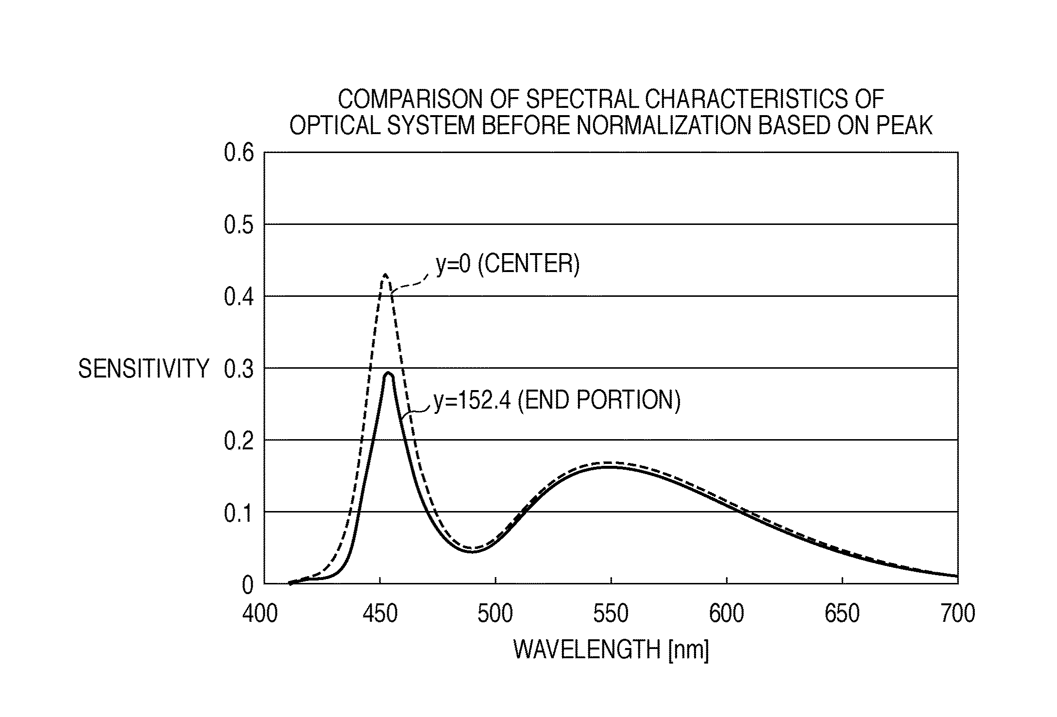
However, shading correction using the white reference member is possible only for light amount variations which are not related to the spectral characteristic (spectral optical characteristic) of the reading optical system, such as the illuminance unevenness of the light source or the decrease in the light amount around the imaging lens.
That is, it is impossible to correct the influence of a change in the spectral characteristic caused by the difference in the angle of view between the reflecting mirror, the imaging mirror, and the imaging lens.
However, when the light reflected by the original is chromatic color light, the main-scanning read luminance becomes uneven even after shading correction.
This is because the shading correction, which is performed based on light of a peak wavelength of white light, cannot completely correct shading of chromatic color light that is different from the peak wavelength.
This problem can arise both in reading a chromatic color using an RGB line sensor and in reading a chromatic color using a monochrome line sensor to be described later.
However, since a longer optical path leads to an increase in the size of the image reading apparatus, the object to obtain a compact apparatus cannot be achieved.
In this method, however, since the number of reference members that require density management increases, the cost increases inevitably.
This makes the shading correction circuit larger and more complex.

Method used


Image

  • Image reading apparatus and image forming apparatus capable of adjusting the difference between the spectral characteristics
  • Image reading apparatus and image forming apparatus capable of adjusting the difference between the spectral characteristics
  • Image reading apparatus and image forming apparatus capable of adjusting the difference between the spectral characteristics

Examples


Embodiment Construction

[0061]An embodiment of the present invention will now be described. Individual embodiments to be described below will serve to understand various concepts including the superordinate concept, intermediate concept, and subordinate concept of the present invention. The scope of the invention is determined by the appended claims which follow the description and is not limited to the individual embodiments to be described below.

[0062]The present invention reduces unevenness in main-scanning read luminance not only when a line sensor for monochrome reading reads a chromatic color but also when an RGB 3-line sensor for color reading reads a chromatic color.

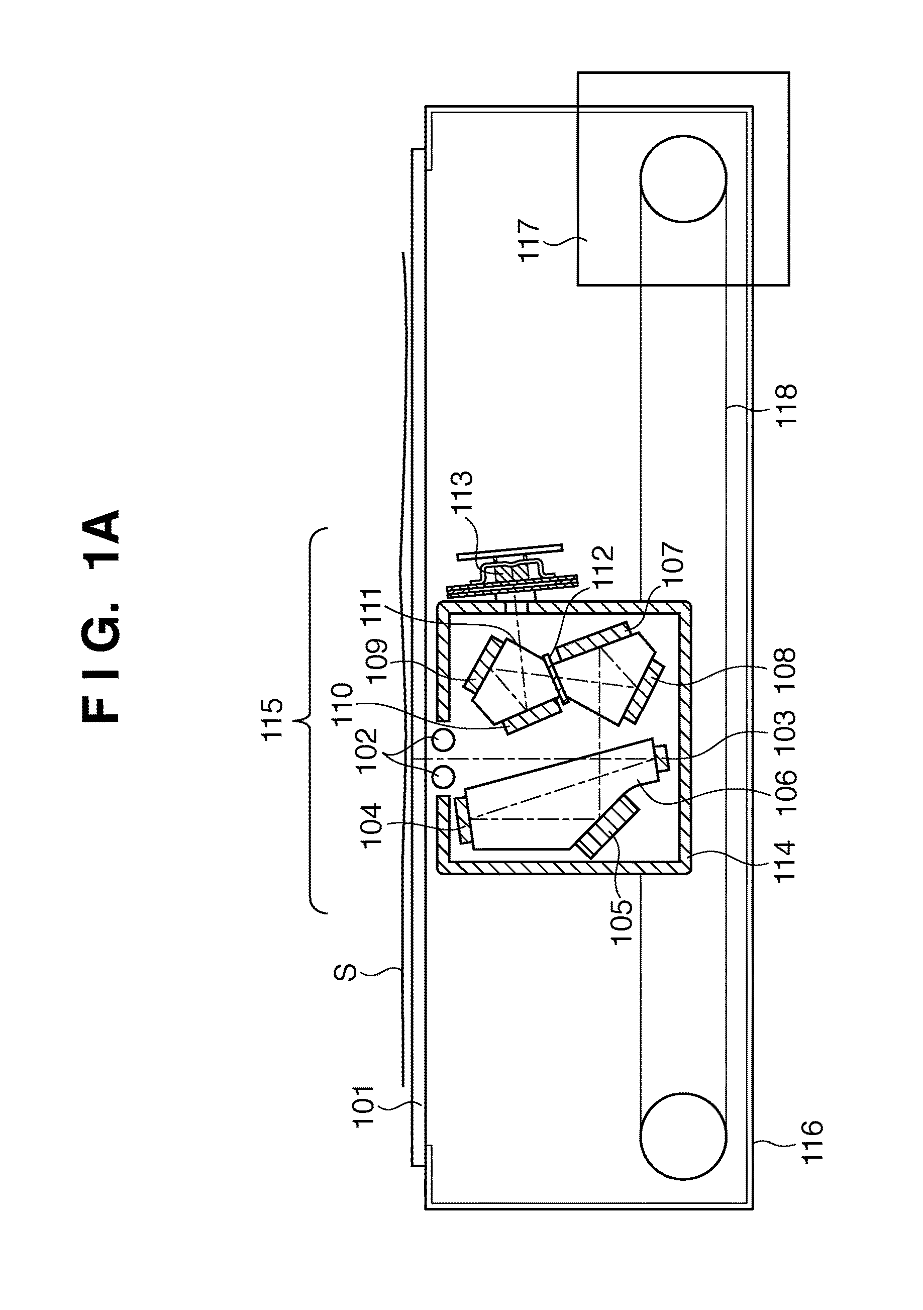
[0063]In the following embodiment, an image reading apparatus will be described which employs an image sensor of 4-line sensor type including an RGB 3-line sensor for color reading and a line sensor for monochrome reading. Unevenness in the read luminance of a chromatic color read by the line sensor for monochrome reading will be explai...


PUM


Abstract

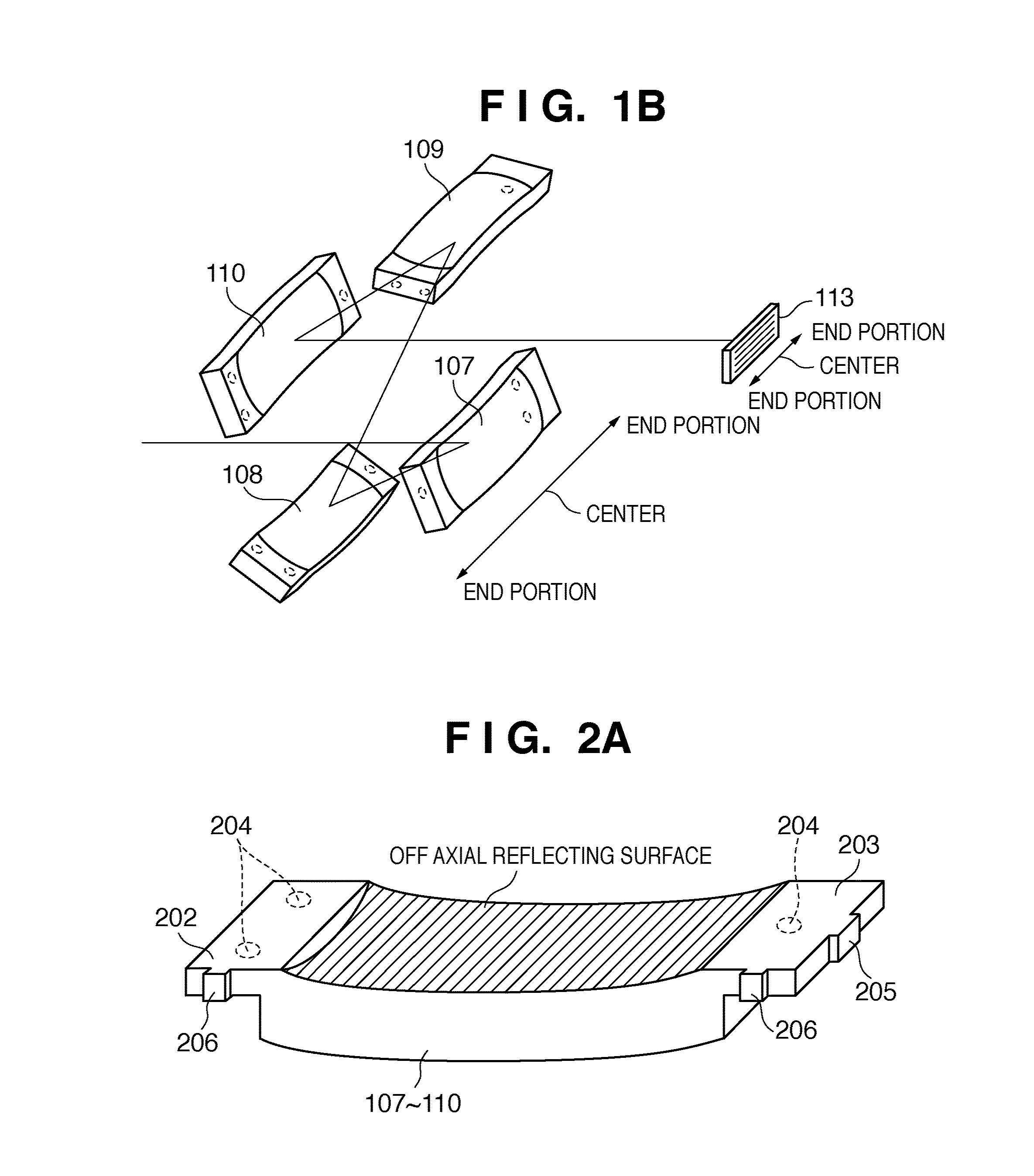
An image reading apparatus includes a light source which irradiates an original with light, an imaging unit which images by condensing reflected and scattered light from the original via a plurality of reflecting mirrors and imaging mirrors, and a photoelectric conversion unit which converts, into an electrical signal, the reflected and scattered light imaged by the imaging unit. The imaging unit is an imaging optical system which is adjusted such that the difference between the spectral characteristic at an end portion in the main-scanning direction of the image reading apparatus and that at the central portion in the main-scanning direction becomes 5% or less at the peak wavelength of the light source.

Description

BACKGROUND OF THE INVENTION[0001]1. Field of the Invention[0002]The present invention relates to an image reading apparatus used together with an image forming apparatus and an image reading apparatus used singly.[0003]2. Description of the Related Art[0004]In general, an image reading apparatus mounted on a digital copying machine or the like includes an imaging lens, a line sensor, and a reflecting mirror (Japanese Patent Laid-Open No. 3-113961). The imaging lens and the line sensor are fixed in a housing. On the other hand, the reflecting mirror is mounted on a movable scanning unit to move in the sub-scanning direction with respect to an original. In the image reading apparatus described in Japanese Patent Laid-Open No. 3-113961, the maximum angle of view is generally designed to be almost 20°.[0005]FIG. 29 is a plan view for explaining the angle of view in an image reading apparatus. The vertical direction of FIG. 29 corresponds to the main-scanning direction of the image readi...

Claims


Application Information

Patent Timeline
Patent Type & Authority Patents(United States)
IPC IPC(8): G06F3/12H04N1/00H04N1/46G03G15/02G03G15/00G03G15/041
CPCG02B17/0647H04N1/03H04N1/0303H04N1/0305H04N1/401H04N1/486G02B7/182H04N1/1017H04N1/193
Inventor MORIKAWA, DAISUKE
Owner CANON KK
Learn More