Supercharge Your Innovation With Domain-Expert AI Agents!

Developing device and image forming apparatus using the same

a technology of developing device and image forming apparatus, which is applied in the direction of electrographic process apparatus, instruments, optics, etc., can solve the problems of uneven image density along the longitudinal direction of the developing roller, change in the volume density of the developer, variation in the developer surface, etc., to reduce the rise of the developer surface, inhibit the stagnation of the developer, and facilitate the flow of the developer

Active Publication Date: 2013-04-02
SHARP KK
View PDF11 Cites 3 Cited by
  • Summary
  • Abstract
  • Description
  • Claims
  • Application Information

AI Technical Summary

Benefits of technology

The solution effectively inhibits developer stagnation and surface height variations, maintaining consistent toner supply and preventing image density unevenness, thereby producing high-quality images.

Problems solved by technology

However, in the developing device that circulatively conveys the developer whilst agitating as shown in patent document 1, if the height of the top surface of the developer (which will be referred to hereinbelow as “the developer surface”) varies along the longitudinal direction of the developing device, the amount of the developer being drawn up by the developing roller (the amount of the developer supplied to the photoreceptor drum) fluctuates, causing the problem of image density unevenness along the longitudinal direction of the developing roller.
Further, when toner is newly added to the developer, the developer presents local variations in toner concentration and in the amount of static charge on the toner, which readily cause change in the volume density of the developer and variation in the developer surface.
In particular, in the developing device of a circulative conveying type, since no conveying member such as an auger screw or the like is disposed at the communication path from one developer conveying passage to the other, the developer, if it is poor in fluidity, is prone to stagnate, triggering marked rise of the developer surface.

Method used


Image

  • Developing device and image forming apparatus using the same
  • Developing device and image forming apparatus using the same
  • Developing device and image forming apparatus using the same

Examples


Embodiment Construction

[0035]Now, the embodied mode for carrying out the present invention will be described with reference to the drawings.

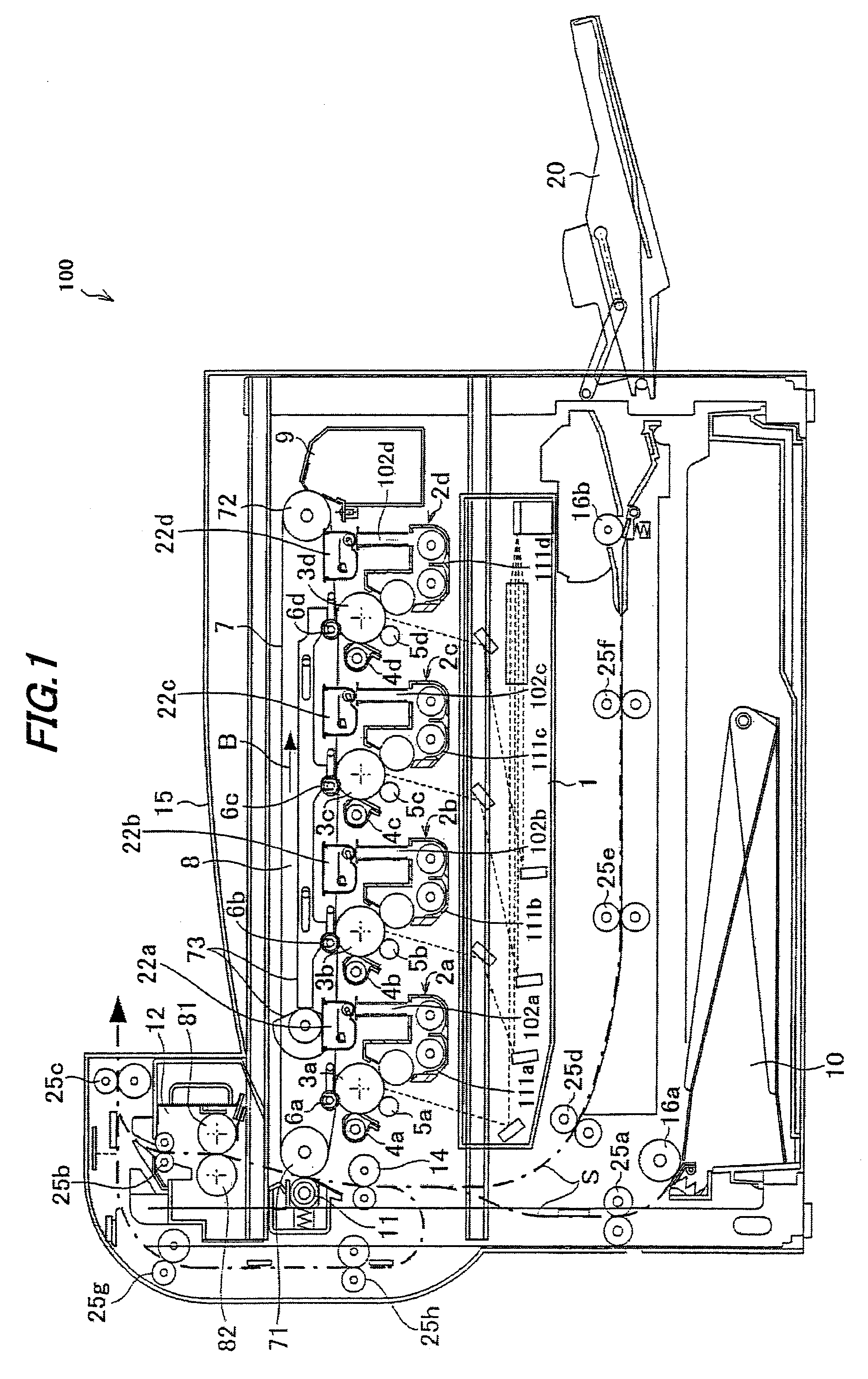
[0036]FIG. 1 shows one exemplary embodiment of the present invention, and is an illustrative view showing the overall configuration of an image forming apparatus including a developing device according to the embodiment of the present invention.

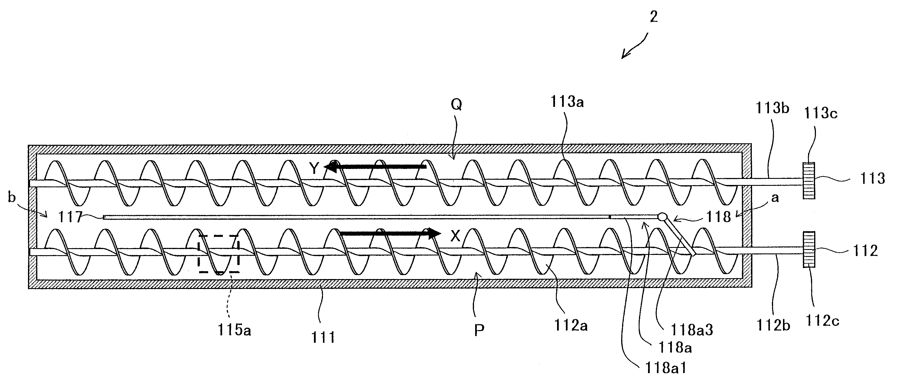
[0037]An image forming apparatus 100 of the present embodiment forms an image with toners based on electrophotography, including: as shown in FIG. 1, photoreceptor drums 3a, 3b, 3c and 3d (which may be also called “photoreceptor drums 3” when general mention is made) for forming electrostatic latent images on the surfaces thereof; chargers (charging devices) 5a, 5b, 5c and 5d (which may be also called “chargers 5” when general mention is made) for charging the surfaces of photoreceptor drums 3; an exposure unit (exposure device) 1 for forming electrostatic latent images on the photoreceptor drum 3 surfaces; developing devices 2...


PUM


Abstract

The developing device includes: a developing container for storing a developer; first and second conveying passages that are formed in the developing container and sectioned by a partition; first and second conveying members disposed inside the first and second conveying passages, respectively, to agitate and circulatively convey the developer through the first and second conveying passages in opposite directions; a developing roller that supplies the developer in the second developer conveying passage to a photoreceptor drum; first and second communication paths that connect between the first and second conveying passages at both ends of the partition; and, a developer flow regulator that regulates the flow of developer moving from the first conveying passage to the second conveying passage, in accordance with the height of the developer surface of the developer.

Description

[0001]This Nonprovisional application claims priority under 35 U.S.C. §119(a) on Patent Application No. 2009-147635 filed in Japan on 22 Jun. 2009, the entire contents of which are hereby incorporated by reference.BACKGROUND OF THE INVENTION[0002](1) Field of the Invention[0003]The present invention relates to a developing device and an image forming apparatus using the device, in particular relating to a developing device using a dual-component developer containing a toner and a magnetic carrier, for use in an image forming apparatus for forming images using the toner based on electrophotography, such as an electrostatic copier, laser printer, facsimile machine or the like, as well as relating to an image forming apparatus using this device.[0004](2) Description of the Prior Art[0005]Conventionally, image forming apparatuses based on electrophotography such as copiers, printers, facsimile machines and the like have been known. The image forming apparatus using electrophotography is...

Claims


Application Information

Patent Timeline
Patent Type & Authority Patents(United States)
IPC IPC(8): G03G15/08
CPCG03G15/0887G03G15/0893G03G15/0853G03G2215/0822G03G2215/0838
Inventor ISHIGURO, YASUYUKIMIHARA, KOICHI
Owner SHARP KK
Features
  • R&D
  • Intellectual Property
  • Life Sciences
  • Materials
  • Tech Scout
  • Unparalleled Data Quality
  • Higher Quality Content
  • 60% Fewer Hallucinations
Learn More