Target for X-ray generation, X-ray generator, and method for producing target for X-ray generation

a technology of x-ray generation and target, which is applied in the direction of x-ray tube targets, x-ray tube targets and convertors, x-ray tube materials, etc., can solve the problems of insufficient heat dissipation from metal wires to substrates, affecting the efficiency of x-ray generation, and increasing the risk of waste of metal wires of the target portion. , to achieve the effect of improving heat dissipation and simplifying production facilities

Active Publication Date: 2013-04-09
HAMAMATSU PHOTONICS KK
View PDF6 Cites 44 Cited by
  • Summary
  • Abstract
  • Description
  • Claims
  • Application Information

AI Technical Summary

Benefits of technology

[0007]It is an object of the present invention to provide an X-ray generation target with improved heat dissipation from the target portion, an X-ray generator, and a method for producing the X-ray generation target.
[0019]The present invention successfully provides the X-ray generation target with improved heat dissipation from the target portion, the X-ray generator, and the method for producing the X-ray generation target.

Problems solved by technology

In this case, however, the side surface of the metal wire is not always in close contact with the inside surface of the hole and a gap can be made between the side surface of the metal wire and the inside surface of the hole.
If the gap is made between the side surface of the metal wire and the inside surface of the hole, it will impede thermal conduction from the metal wire to the substrate.
As a result, heat dissipation from the metal wire will become insufficient and it can make the metal wire of the target portion more likely to waste.
In the configuration wherein the metal wire is buried in the substrate, it is difficult to easily form the nanosized target portion in the substrate.

Method used


Image

  • Target for X-ray generation, X-ray generator, and method for producing target for X-ray generation
  • Target for X-ray generation, X-ray generator, and method for producing target for X-ray generation
  • Target for X-ray generation, X-ray generator, and method for producing target for X-ray generation

Examples


Embodiment Construction

[0035]The preferred embodiments of the present invention will be described below in detail with reference to the accompanying drawings. In the description, identical elements or elements with identical functionality will be denoted by the same reference symbols, without redundant description.

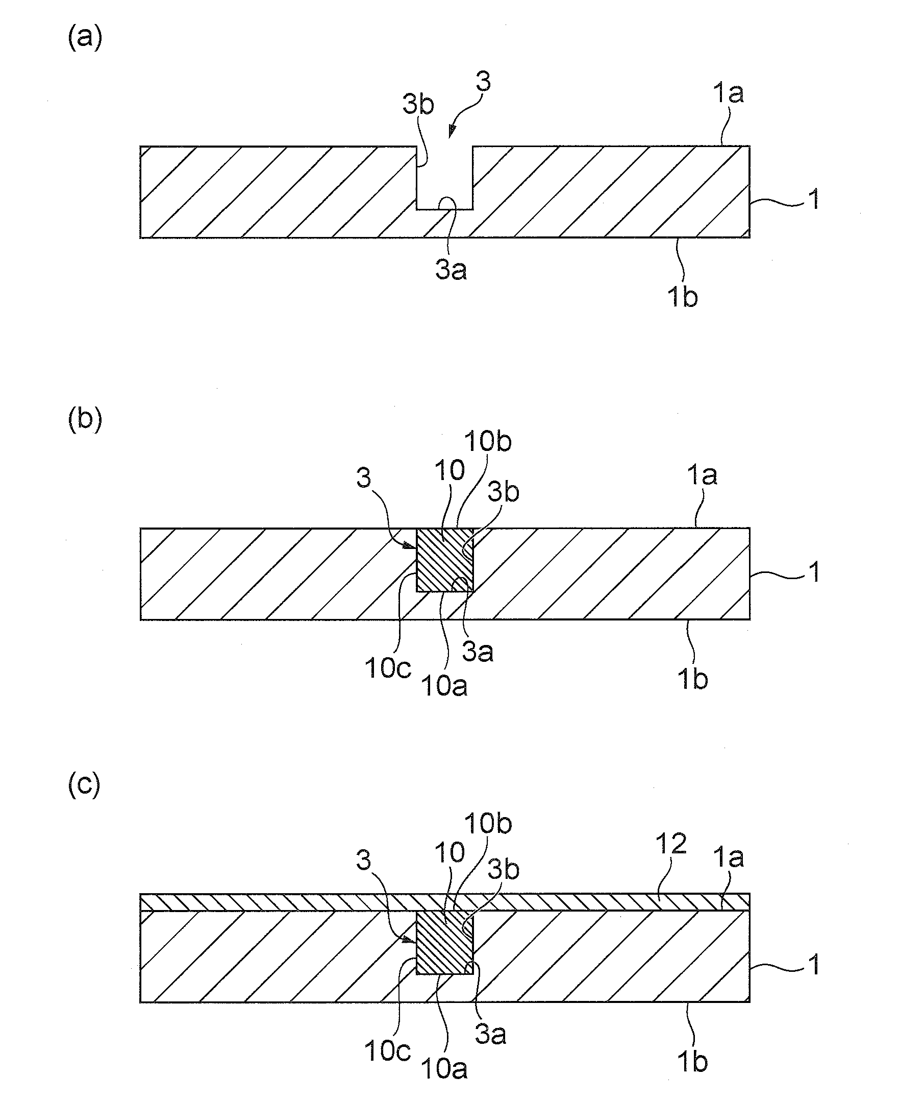
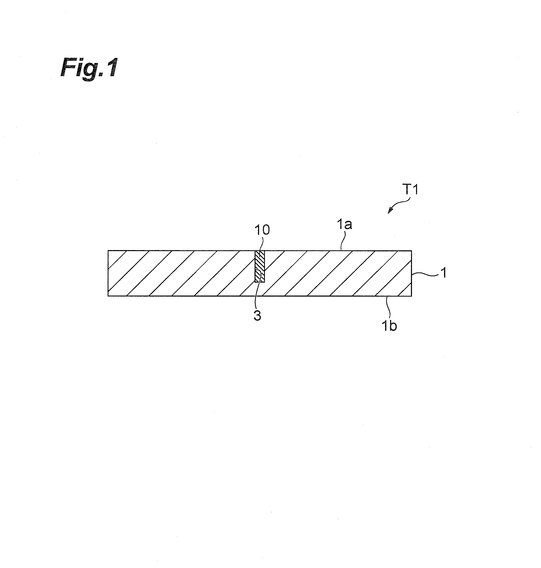
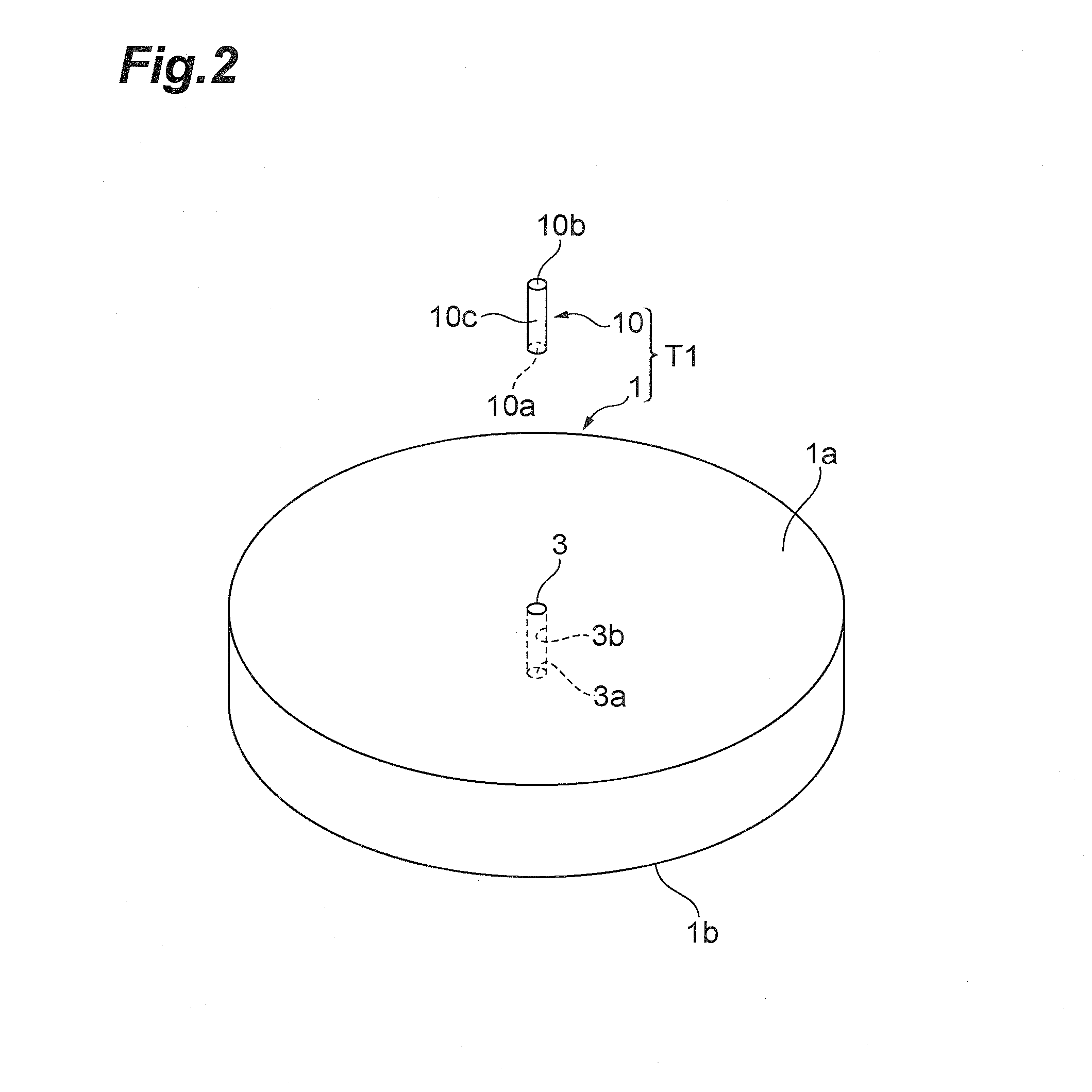
[0036]An X-ray generation target T1 according to an embodiment of the present invention will be described with reference to FIGS. 1 and 2. FIG. 1 is a drawing for explaining a cross-sectional configuration of the X-ray generation target according to the present embodiment. FIG. 2 is an exploded perspective view of the X-ray generation target according to the present embodiment.

[0037]The X-ray generation target T1, as shown in FIGS. 1 and 2, is provided with a substrate 1 and a target portion 10.

[0038]The substrate 1 is comprised of diamond and has a disk shape. The substrate 1 has first and second principal surfaces 1a, 1b opposed to each other. The substrate 1 does not always have to be limited...


PUM

PropertyMeasurementUnit
thicknessaaaaaaaaaa
diameteraaaaaaaaaa
diameteraaaaaaaaaa

Abstract

A target for X-ray generation has a substrate and a target portion. The substrate is comprised of diamond and has a first principal surface and a second principal surface opposed to each other. A bottomed hole is formed from the first principal surface side in the substrate. The target portion is comprised of a metal deposited from a bottom surface of the hole toward the first principal surface. An entire side surface of the target portion is in close contact with an inside surface of the hole.

Description

BACKGROUND OF THE INVENTION[0001]1. Field of the Invention[0002]The present invention relates to a target for X-ray generation (which will be referred to hereinafter as an X-ray generation target) and a production method thereof, and an X-ray generator with the X-ray generation target.[0003]2. Related Background Art[0004]There is a known X-ray generation target provided with a substrate, and a target portion buried in the substrate (e.g., cf. Japanese Patent Application Laid-open No. 2004-028845). In the X-ray generation target described in Japanese Patent Application Laid-open No. 2004-028845, a single columnar metal wire of tungsten or molybdenum is buried in the substrate comprised of a light element such as beryllium or carbon.SUMMARY OF THE INVENTION[0005]For obtaining the X-ray generation target in which the metal wire is buried in the substrate, it is conceivable to form a hole in the substrate and insert the metal wire into the hole. In this case, however, the side surface o...

Claims


Application Information

Patent Timeline
Patent Type & Authority Patents(United States)
IPC IPC(8): H01J35/08
CPCH01J35/12H01J2235/081H01J2235/1291H01J2235/087H01J2235/1204H01J2235/083H01J35/116
Inventor OKUMURA, KATSUYAKADOSAWA, KATSUJIKIYOMOTO, TOMOFUMISUYAMA, MOTOHIROISHII, ATSUSHI
Owner HAMAMATSU PHOTONICS KK
Why Eureka
Try Eureka