
Projectile device and method for targeted vehicle tracking

a technology for vehicle tracking and projectiles, applied in the direction of ammunition projectiles, cartridge ammunition, weapons, etc., can solve the problem of difficult and achieve the effect of eliminating the chance of causing a crash resulting in property damage, injury, or death, and easy removal of such projectiles

Inactive Publication Date: 2013-04-16
MCGARRAUGH JASON THOMAS +1
View PDF11 Cites 5 Cited by
  • Summary
  • Abstract
  • Description
  • Claims
  • Application Information

AI Technical Summary

Benefits of technology

[0012]It is an object of this embodiment of the invention to provide a method for attaching a projectile fired from a high powered compressed air cannon at a suspect vehicle, and attaching it with the idea that removal of such projectile is not easy. It is an object of this embodiment to be able to be used during a high speed police chase, with no reasonable limitation of measured speed on a legal roadway. It is an object of this embodiment to eliminate high speed police chases using said embodiment and included GPS tracking systems, and statistically eliminate the chance of causing a crash resulting in property damage, injury, and or death. It is an object of this embodiment, when projectile is loaded with said GPS tracking equipment, and remote activated explosives, to be utilized in an armed forces scenario, specifically in a densely populated area, where a target has been acquired, and the need for the threat to be eliminated, the projectile can be fired by desired cannon to the threat, and subsequently tracked as the vehicle or conveyance retreats away from such a populated area where detonation is less likely to cause collateral damage. It is an object of this embodiment for the invention to cause damage to the target being fired at, allowing for the unique non obvious method of attachment to work.

Problems solved by technology

The tip of this projectile has a retention cross that, while impacting the target, decelerates the penetration shaft containing a blank charge, while the outer housing containing a firing pin continues forward, impacting and thus firing the charge, explosively forcing the penetration shaft forward towards the impact point on the targets surface, where the pointed tip penetrates the surface, makes a hole and the barbs of the retention cross catch the lip of the now serrated material around the diameter of the hole, and locks it into place, making removal extremely difficult.

Method used


Image

  • Projectile device and method for targeted vehicle tracking
  • Projectile device and method for targeted vehicle tracking
  • Projectile device and method for targeted vehicle tracking

Examples


Embodiment Construction

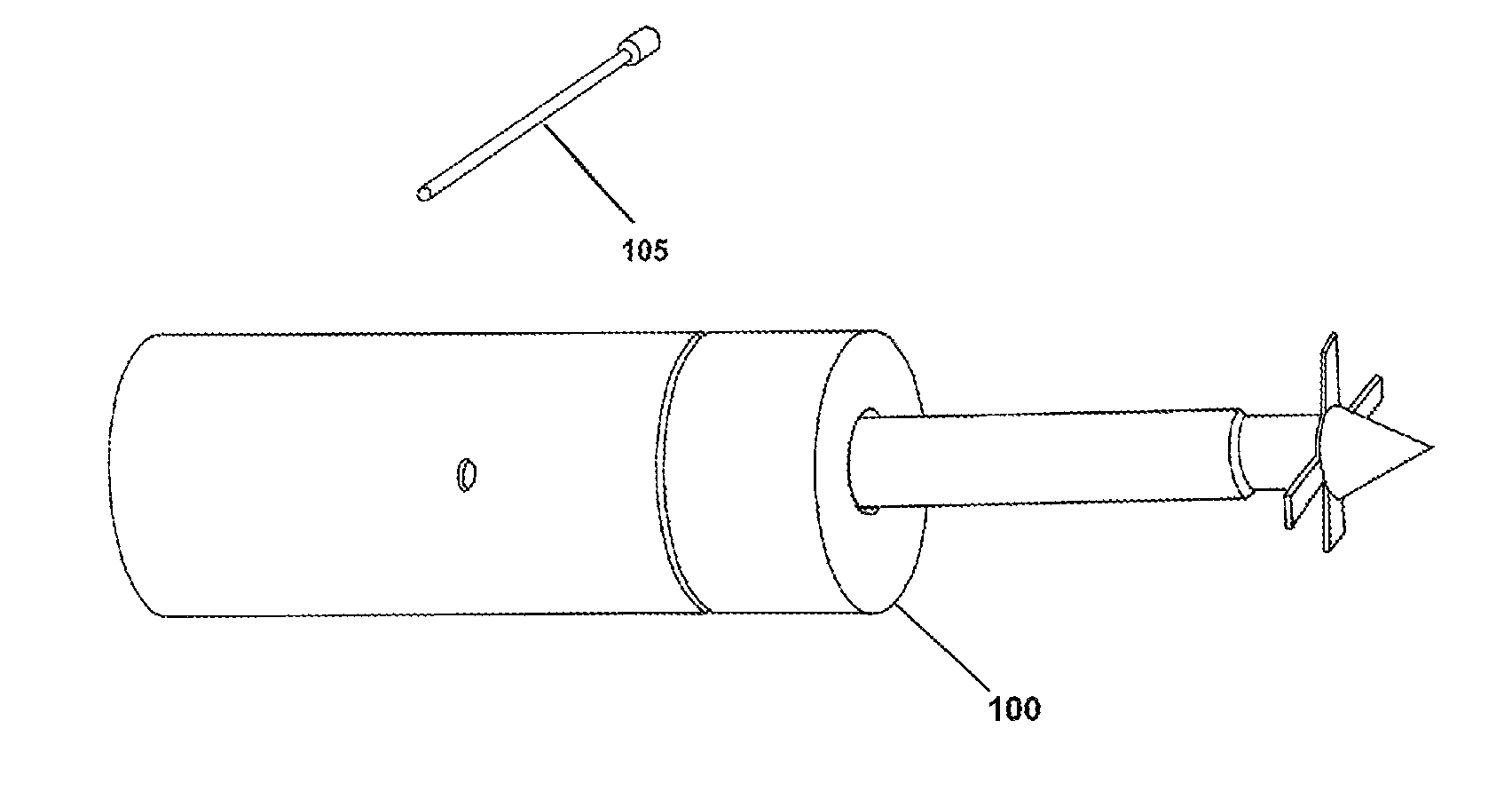
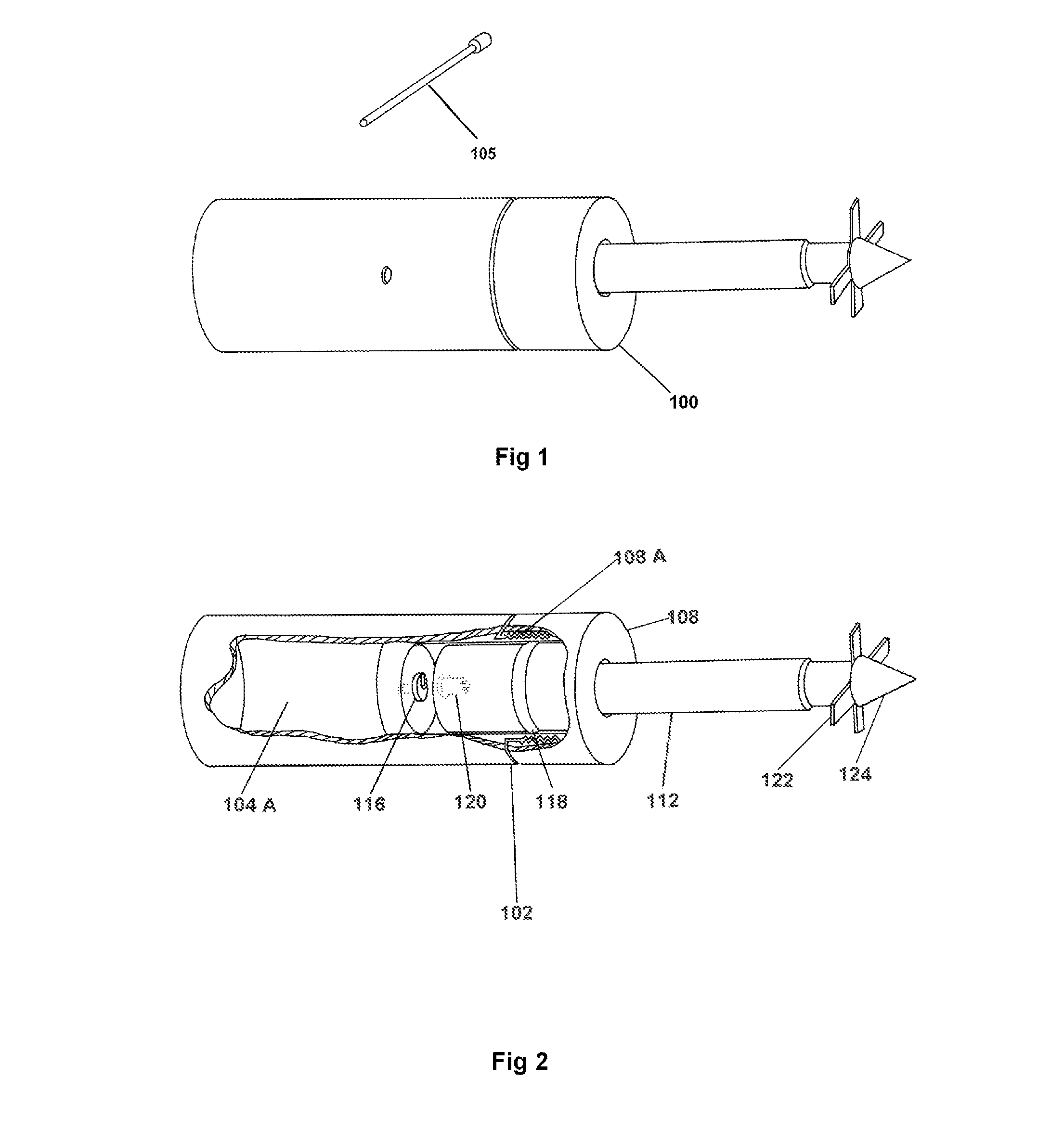
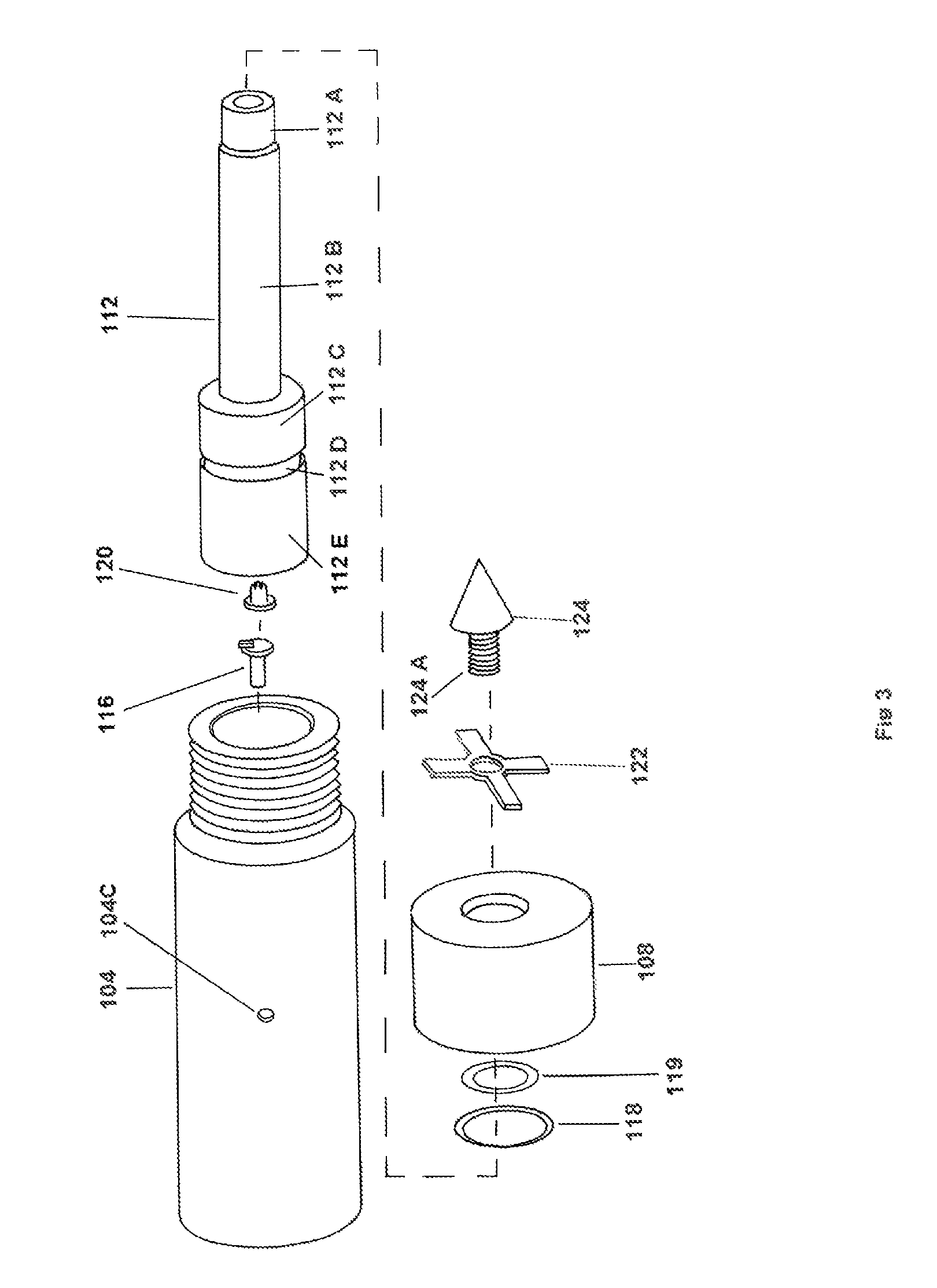
[0068]The present invention, as presented in FIGS. 1-12, is a projectile device generally comprising an outer containment housing, a penetration shaft extending from the outer containment housing, a tip attached to an end of the penetration shaft, a retention cross attached to the tip, within the outer containment housing is provided a charged round, a firing mechanism having a firing pin, a force recognition sensor, a power source, a data transmission and receiving device, a sensor recognition device and a data retrieval antennae and wherein the projectile device is formed as an aerodynamic cylindrical unit.

[0069]The projectile device 100 includes a pointed impact tip 124, a retention cross 122, a cap 108, a large O-ring 118, a small O-ring 119, a penetration shaft 112, a blank charge 120, a firing mechanism including a firing pin 116, and an outer housing 104. The safety pin 105 is of a cylindrical shape and size that will fit into the safety pin holes 104-C to block the firing pi...


PUM


Abstract

An invention in which a projectile device is deployed from a compressed air firing system that, upon impact of the projectile device into a target, the projectile device embeds itself in the intended target's outer surface or material. In one application, a GPS receiver and transmitter provided within the projectile device relays position data to a receiving apparatus that is monitored by a stationary or mobile conveyance. In another application, the projectile device, may include remotely operable explosives which are preferably triggered once the target is an area where the explosives can be detonated with minimal collateral damage.

Description

[0001]This Application relates to Provisional Application 61 / 152,479 Filed 13 Feb. 2009FIELD OF INVENTION[0002]The present invention relates to projectile device for deploying and impaling into a target.BACKGROUND OF INVENTION[0003]There is a world wide upsurge in episodes of criminal activity regarding the operation of motorized vehicles, and or mobile mechanical conveyances. Citizens placed in a position of confrontation or under rule of authority for insignificant and / or malicious infractions or crimes deviate from authorized direction by such authorities to cease operation of said conveyances. When they fail to stop, the level of violation and resistance committed is significantly raised.[0004]Under a civilian crisis, as in a traffic stop where the violator refuses to cease operation of a vehicle and continues on a course simply away from the pursuing agent of authority, the propensity for intense biological stress upon the operators has been shown to limit logical decision maki...

Claims


Application Information

Patent Timeline
Patent Type & Authority Patents(United States)
IPC IPC(8): F42B6/00F42B12/00F42B30/00
CPCF42B12/365
Inventor MCGARRAUGH, JASON THOMASMILLER, BARRON CHRISTOPHER
Owner MCGARRAUGH JASON THOMAS
Learn More