Flow guide

a flow guide and flow technology, applied in the field of flow guides, can solve the problems of increasing surgical theatre time and patient being under general anesthesia, affecting the visualisation of laparoscopic images, and affecting the patient's general anesthesia, so as to facilitate flow divergence, facilitate flow separation, and facilitate the effect of flow divergen

Active Publication Date: 2013-04-16
ENDOGUARD
View PDF91 Cites 28 Cited by
  • Summary
  • Abstract
  • Description
  • Claims
  • Application Information

AI Technical Summary

Benefits of technology

[0014]In some embodiments, the flow guide is for guiding and directing the fluid flow to clear an end surface of the device. In some embodiments, the device is an endoscope and the end surface comprises the surface of the optics (such as a lens surface). The flow guide allows the surface of the lens to be cleaned of any biological or foreign material that becomes attached to the lens during surgery. The lens can therefore be cleaned without the endoscope having to be removed from the patient and this ensures that the surgeon can visualise the surgical site at all times.
[0020]In some embodiments, the flow guide is configured such that a portion of the device or endoscope extends longitudinally clear beyond a lowered portion of the flow guide transversely opposite the outlet. This enables the flow across the end surface to clear the end surface more efficiently at its edges, thereby facilitating cleaning of the end surface. In other words, in these embodiments, there is a gap between the lowered portion and the plane in which the end surface is disposed in use. For example, the lowered portion may extend on each side of the outlet or any other guide arrangements adjacent the outlet, such as the limbs described above. The lowered portion may extend over the entire remaining perimeter of the flow guide, whether the flow guide completely encloses the device or encloses it only partially.

Problems solved by technology

Since these instruments are a crucial part of MIS and laparoscopic procedures, in general, they will remain as the main source of lens contamination.
As a result of this contamination, visualisation via the laparoscope optics is regularly diminished and impaired.
During this period, the patient can be exposed to increased risk since the surgeon can no longer see the operating field.
Further to this, there is an interruption in surgeon workflow and an increase in surgical theatre time and time of the patient being under general anaesthesia.
However, more importantly, the surgeon's workflow and concentration is broken, compromising patient safety.
These attempts have been inadequate at solving the myriad of problems associated with cleaning the lens in-situ.

Method used


Image

  • Flow guide
  • Flow guide
  • Flow guide

Examples


Embodiment Construction

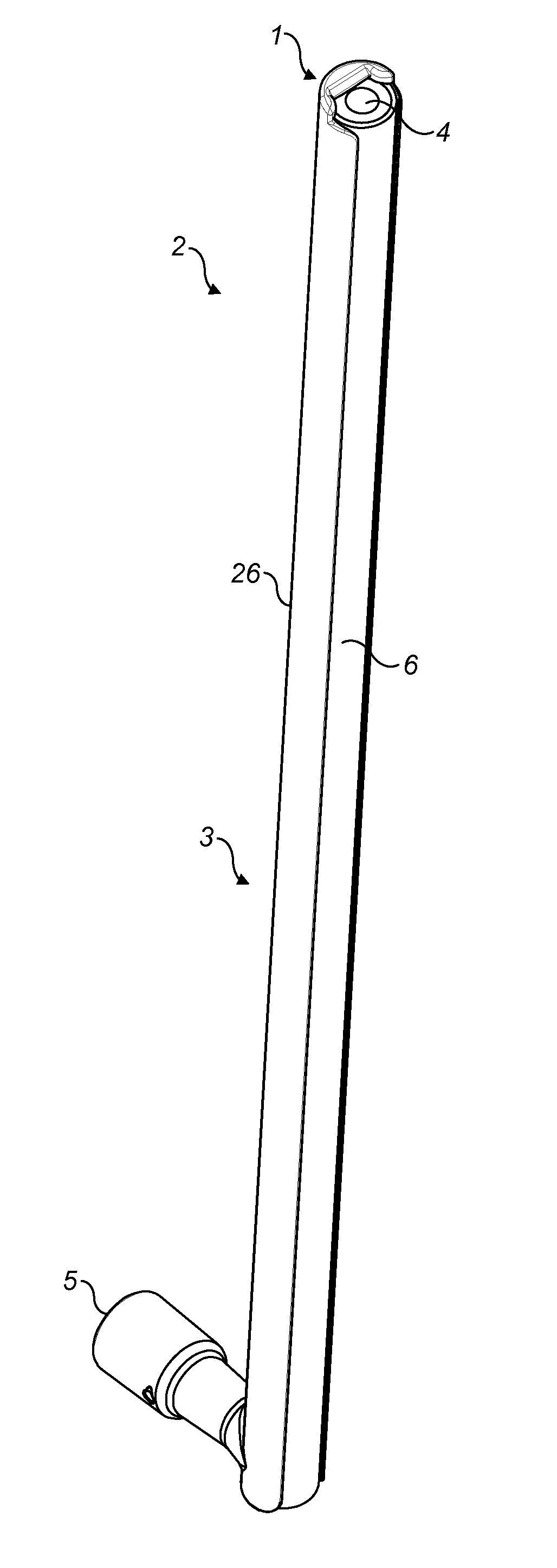
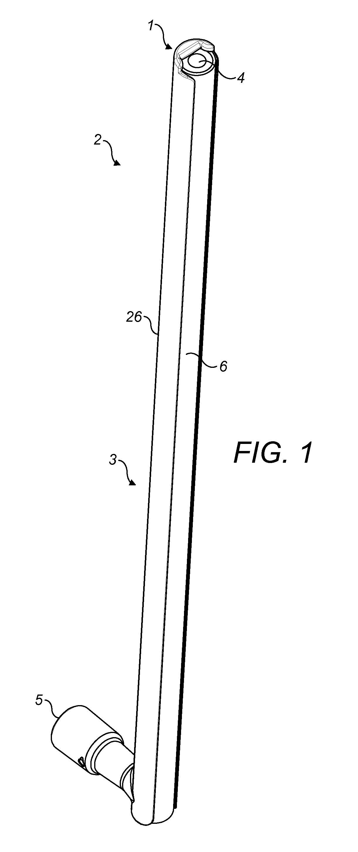
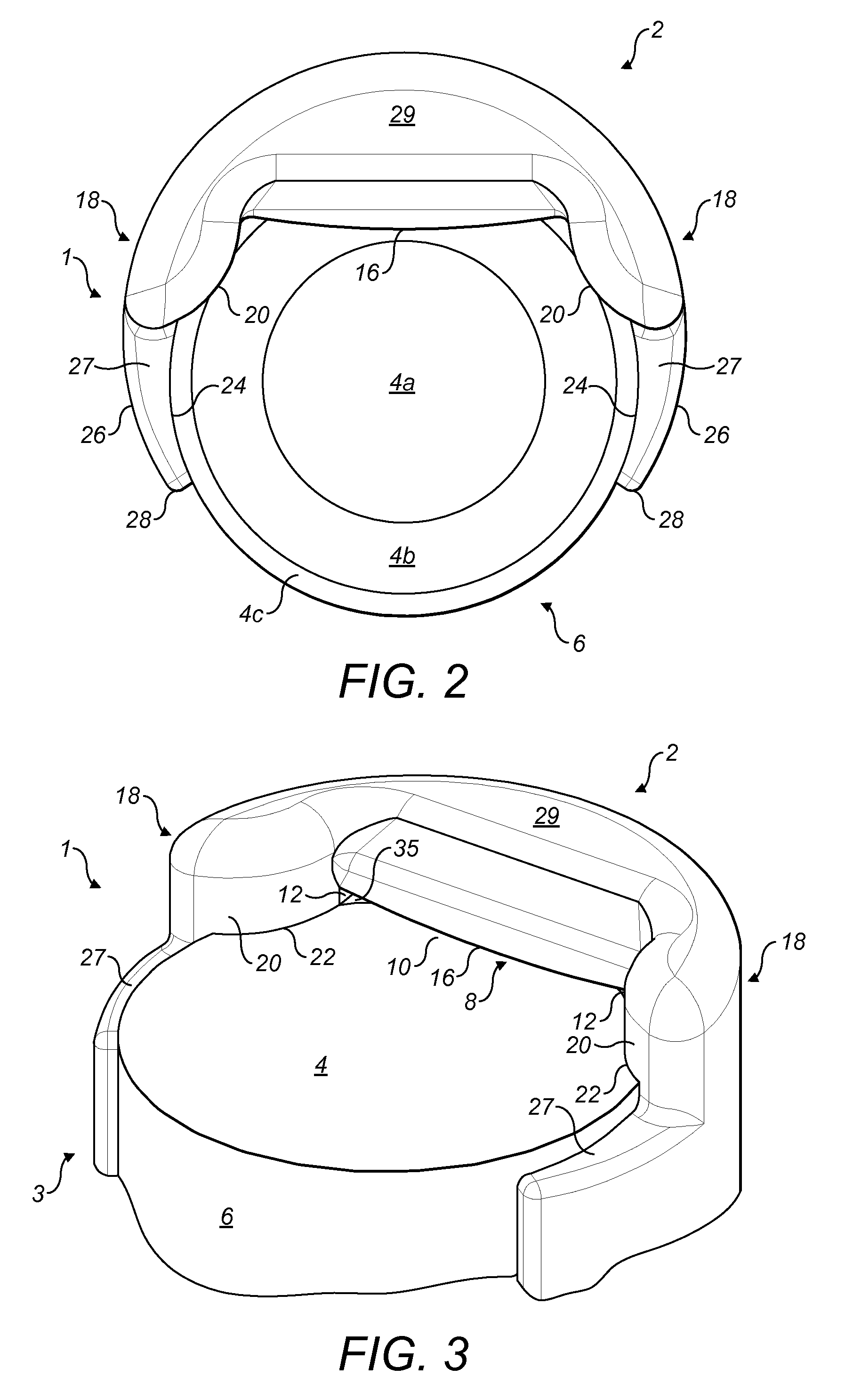
[0060]With reference to FIG. 1, a flow guide 2 is attached to a laparoscope 6, which is generally cylindrical or rod-shaped. The flow guide 2 is for guiding a fluid flow longitudinally along the laparoscope 6 and directing the fluid flow across a substantially flat distal end surface 4 of the laparoscope 6. The flow guide 2 is arranged to promote laminar flow of the fluid across the end surface 4 of the laparoscope 6. The flow guide 2 comprises a longitudinal portion 3 for guiding the fluid flow in a longitudinal direction along the shaft of the laparoscope 6, a distal end portion 1 for directing the fluid flow across the end surface 4 to clean the end surface 4 and an inlet 5 at an opposite end. The end surface 4 (shown in more detail in FIG. 2) is disposed generally in a transverse plane. (i.e. a plane, perpendicular to the longitudinal direction, that is fixed relative to the flow guide 2) and comprises a lens 4a, optical window, or other surface of the laparoscope 6, surrounded ...


PUM


Abstract

A flow guide directs a fluid flow across a surface of a device, for example a lens surface of an endoscope, in a controlled manner to facilitate flow attachment to the surface. Embodiments include features that impart a non-uniform velocity profile and / or include guide surfaces for facilitating flow attachment and / or coverage.

Description

CROSS-REFERENCE TO RELATED APPLICATION[0001]This application claims priority to Application No. 0917857.5 filed on Oct. 12, 2009 in Great Britain.FIELD OF THE INVENTION[0002]The present invention relates to a flow guide for directing a fluid flow across a surface of a device in a controlled manner. Particularly, but not exclusively, the device is an endoscope and the surface comprises a surface of a lens or other optical surface.[0003]The present invention will be discussed in relation to the optics of an endoscope and, in particular, with reference to that of a laparoscope, but by no means is it exclusive to these devices. It can also encompass commercial or other medical optic instrumentation as well as other devices.BACKGROUND OF THE INVENTION[0004]Endoscopes are used in minimally invasive surgery (MIS) by surgeons to permit remote visualisation and navigation within a body cavity inside a patient. They act as the eyes of the surgeon whilst a surgical procedure, tissue manipulati...

Claims


Application Information

Patent Timeline
Patent Type & Authority Patents(United States)
IPC IPC(8): A61B1/12A61B1/00
CPCA61B1/00091A61B1/3132A61B1/126A61B1/00135A61B1/121A61B1/127
Inventor JAMES, ADAM GRAHAMCHEN, JIEWILLS, ANTHONY ARTHUR
Owner ENDOGUARD
Why Eureka
Try Eureka