
End cover assembly for an electrochemical cell

a battery cell and end cover technology, applied in the field of lithium ion battery cells and systems, can solve the problems of increasing public awareness of cost and environmental issues, deficient battery systems for use with electric motors employed in pure electric and hybrid vehicles, and inability to meet the needs of electric motors,

Active Publication Date: 2013-04-16
BYD CO LTD
View PDF104 Cites 8 Cited by
  • Summary
  • Abstract
  • Description
  • Claims
  • Application Information

AI Technical Summary

Benefits of technology

This patent describes an end cover assembly for a battery, which includes a cover plate with an opening, a scabbard with an interior channel that connects to the opening, and a connector that extends from the scabbard and is in electrical contact with the battery's core. The assembly also includes a sealing material that wraps around the scabbard and helps protect the battery from damage. The technical effect of this invention is to provide a reliable and safe closure for battery shells, ensuring optimal protection and performance of the battery.

Problems solved by technology

The public has become increasingly sensitive to cost and environmental issues associated with the use of fossil-based fuels.
Battery systems for use with electric motors employed in pure electric and hybrid vehicles are currently deficient in many respects.
Individual battery cells of the battery system are frequently heavy, bulky, and unreliable.
Further, current battery cells are neither constructed nor used to effectively provide the high power output needed to accelerate the vehicle at an acceptable acceleration level.
Still further, individual battery cells use electrochemistry, cell core constructions, electrical interconnections, and shell constructions that are often unreliable, unsafe, and generally not suitable for use in electrical powered vehicles.
The interconnections between the individual battery cells, again, are often unreliable.
Further, little has been accomplished to ensure the safety of such multi-cell battery systems.
Short-circuits as well as explosions have not been adequately addressed.

Method used


Image

  • End cover assembly for an electrochemical cell
  • End cover assembly for an electrochemical cell
  • End cover assembly for an electrochemical cell

Examples


Embodiment Construction

[0071]Lithium-ion polymer batteries are a type of rechargeable battery in which a lithium ion moves between an anode and cathode. The lithium ion moves from the anode to the cathode during discharge and from the cathode to the anode when charging.

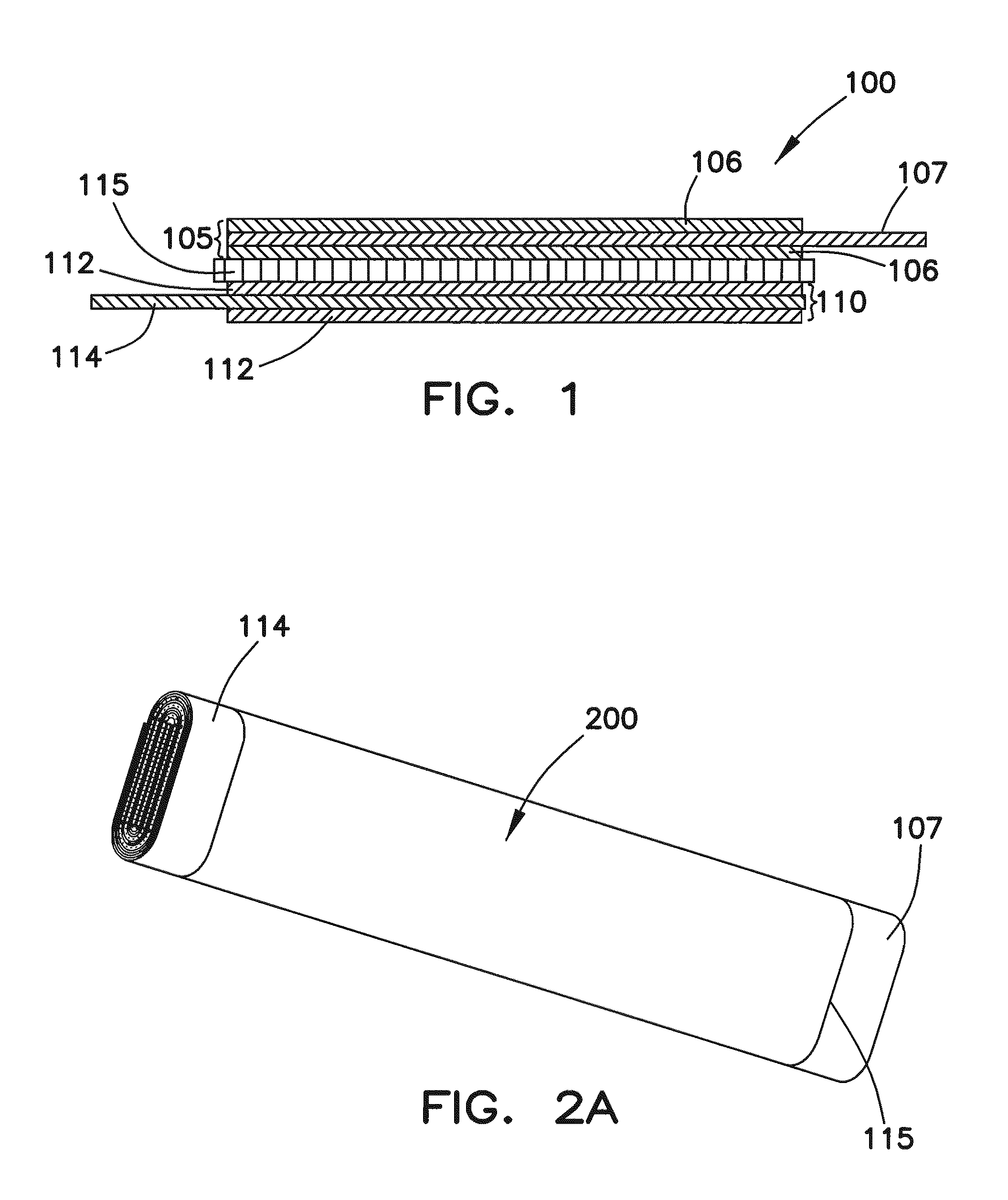
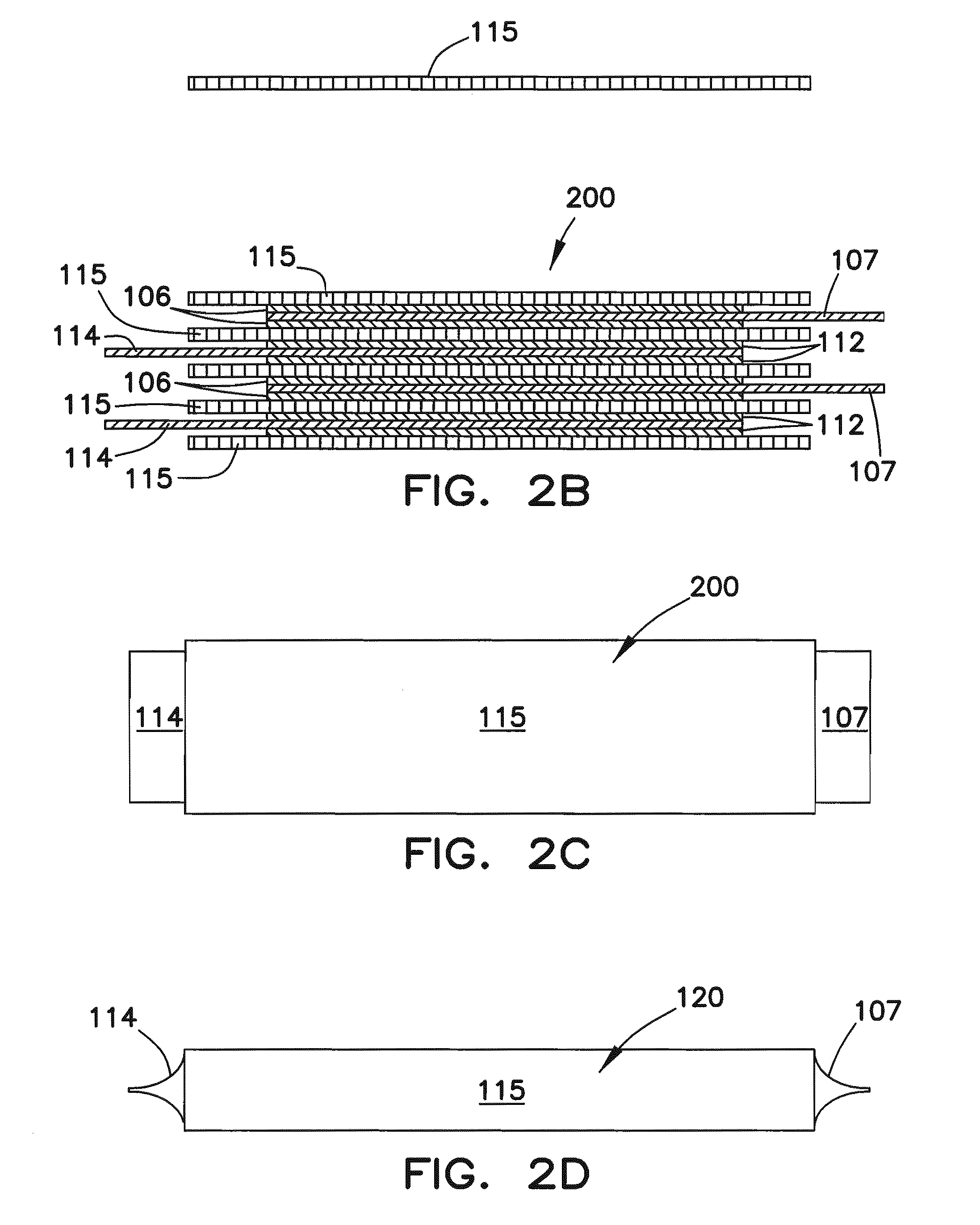
[0072]FIG. 1 is a cross-sectional view through an exemplary multilayer battery sheet 100 that may be wound to form a coiled battery core. The battery sheet 100 of FIG. 1 includes three functional components: an anode sheet 105, a cathode sheet 110, and a separator sheet 115. The anode sheet 105 may include active anode layers 106 disposed on opposite sides of an anode substrate 107. The anode substrate 107 may be formed from one or more layers of a metal foil, such as copper. The active anode layers 106 may be formed from graphite or other carbon-based material. In one example, active layers 106 of the anode sheet 105 may be produced using 100 grams of natural graphite with 3 grams of polyvinylidene fluoride (PVDF) binder material and 3 gra...


PUM

PropertyMeasurementUnit
thicknessaaaaaaaaaa
thicknessaaaaaaaaaa
temperatureaaaaaaaaaa

Abstract

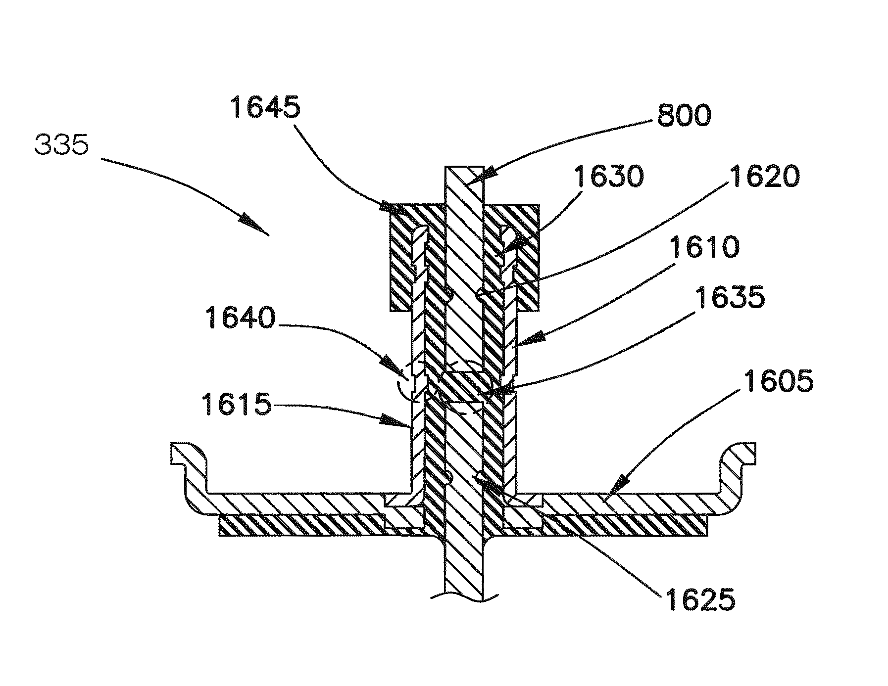
An end cover assembly for a battery comprises a cover plate; a scabbard mounted on the cover plate; a connector; and a sealing material. The cover plate comprises an opening. The scabbard comprises an interior channel. The opening is in communication with the channel. The connector is disposed in the interior channel and protrudes from the scabbard. The sealing material is disposed in the interior channel and extends beyond the upper portion of the scabbard and wraps around the outside of the scabbard to form a protective flange.

Description

RELATED U.S. APPLICATION DATA[0001]Continuation-in-part of application Ser. Nos. 12 / 341,808 filed Dec. 22, 2008, now U.S. Pat. No. 8,202,644 and 12 / 341,704, filed on Dec. 22, 2008, and PCT application No. PCT / CN2008 / 073678, filed on Dec. 24, 2008, which claim priority to the following Patent Applications:[0002]Application Number 200720196395.2, filed Dec. 25, 2007;[0003]Application Number 200820116496.9, filed Jun. 30, 2008;[0004]Application Number 200810145734.3, filed Aug. 14, 2008;[0005]Application Number 200810135478, filed Aug. 7, 2008;[0006]Application Number 200810135477.5, filed Aug. 7, 2008;[0007]Application Number 200810142082.8, filed Aug. 26, 2008;[0008]Application Number 200810142090.2, filed Aug. 26, 2008;[0009]Application Number 200810142083.2, filed Aug. 26, 2008;[0010]Application Number 200820146848.5, filed Aug. 26, 2008;[0011]Application Number 200820146851.7, filed Aug. 26, 2008;[0012]Application Number 200820146849.X, filed Aug. 26, 2008;[0013]Application Number...

Claims


Application Information

Patent Timeline
Patent Type & Authority Patents(United States)
IPC IPC(8): H01M2/24H01M50/529H01M50/147H01M50/176H01M50/188H01M50/191H01M50/469H01M50/503H01M50/51H01M50/512H01M50/593
CPCH01M2/04H01M2/08H01M2/1094H01M2/1241H01M2/1673H01M2/18H01M2/202H01M2/22H01M2/347H01M10/0525H01M10/0587H01M10/486H01M10/5004H01M10/5006H01M10/5016H01M10/5032H01M10/5051H01M10/5057H01M10/5075H01M10/5083H01M10/5093H01M2/06Y10T156/10H01M10/504H01M2200/00Y02E60/122Y02T10/7011Y10T29/49108H01M10/625H01M10/6553H01M10/615H01M10/653H01M10/647H01M10/6556H01M10/6571H01M10/6567H01M10/66H01M10/613Y02E60/10H01M50/147H01M50/24H01M50/3425H01M50/46H01M50/528H01M50/579Y02P70/50H01M50/512H01M50/503H01M50/593H01M50/469H01M50/51H01M50/176H01M50/188H01M50/191Y02T10/70
Inventor ZHU, JIANHUAZHOU, HAO
Owner BYD CO LTD
Learn More