
Water wheel comprising a built-in generator

a generator and water wheel technology, applied in the direction of motors, dynamo-electric machines, tidal streams/damless hydropower, etc., can solve the problems of reducing efficiency, movable parts are subject to wear, and requiring complex or costly maintenance, etc., to achieve simple construction and easy transportation

Active Publication Date: 2013-04-16
DREWS HARTMUTH
View PDF45 Cites 8 Cited by
  • Summary
  • Abstract
  • Description
  • Claims
  • Application Information

AI Technical Summary

Benefits of technology

This invention is about a new type of generator that is easy to move and assemble. It uses a simple design with a rotor and stator that can be adapted to different situations. The generator can be designed based on the size of the water wheel, which makes it portable and easy to assemble. The stator can be segmented to allow for flexibility and improved efficiency. The permanent magnets on the rotor can be arranged on different sides of the ring element, and a combination of areas can be used for increased efficiency. Overall, this invention offers a simplified and adaptable generator design that is easy to move and assemble.

Problems solved by technology

Thereby, relatively heavy and expensive structural components arise.
These known arrangements have a reduced efficiency, especially due to the mechanical transmission losses.
Furthermore, the movable parts are subject to wear and require a complex or costly maintenance.

Method used


Image

  • Water wheel comprising a built-in generator
  • Water wheel comprising a built-in generator
  • Water wheel comprising a built-in generator

Examples


Embodiment Construction

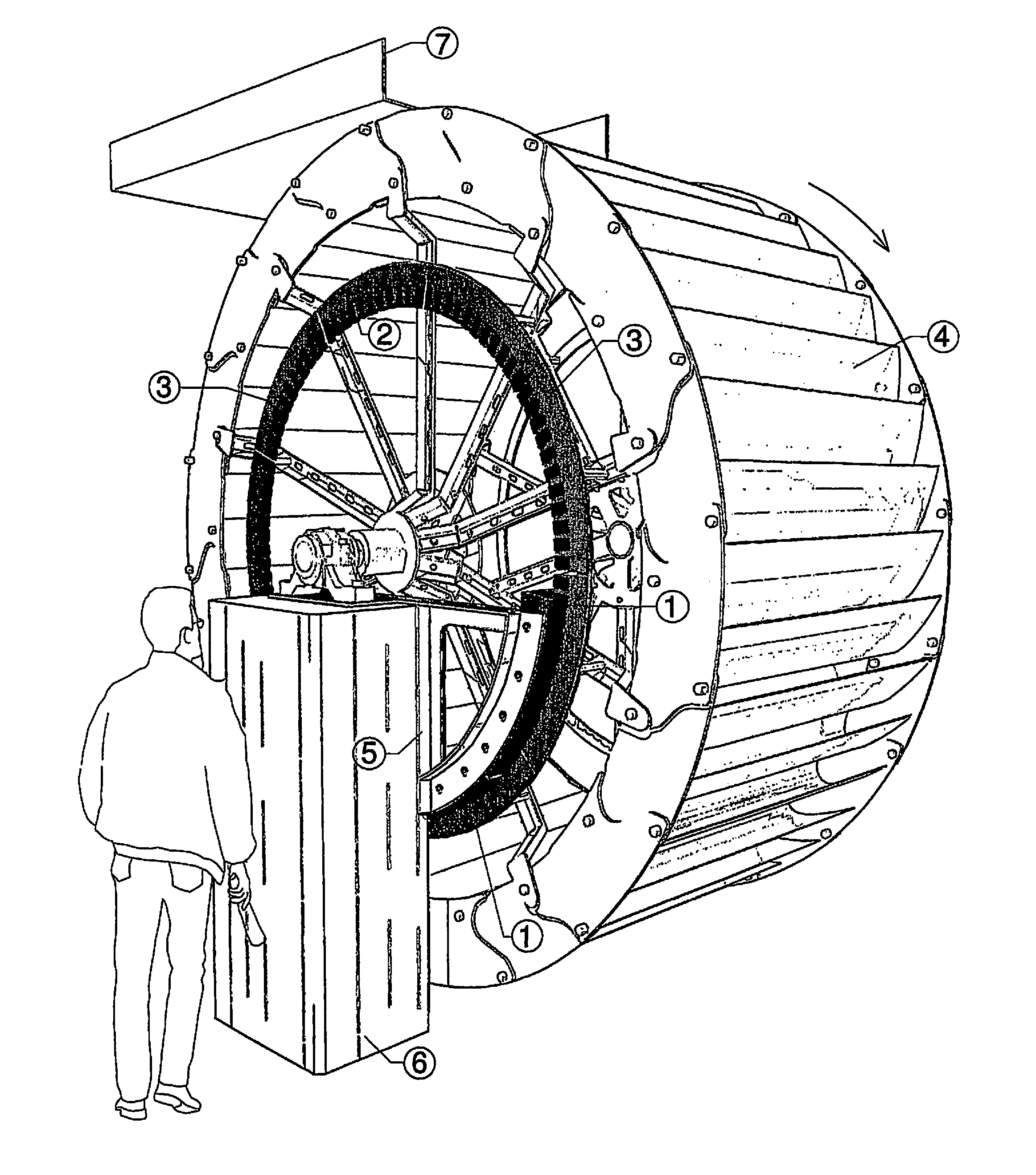
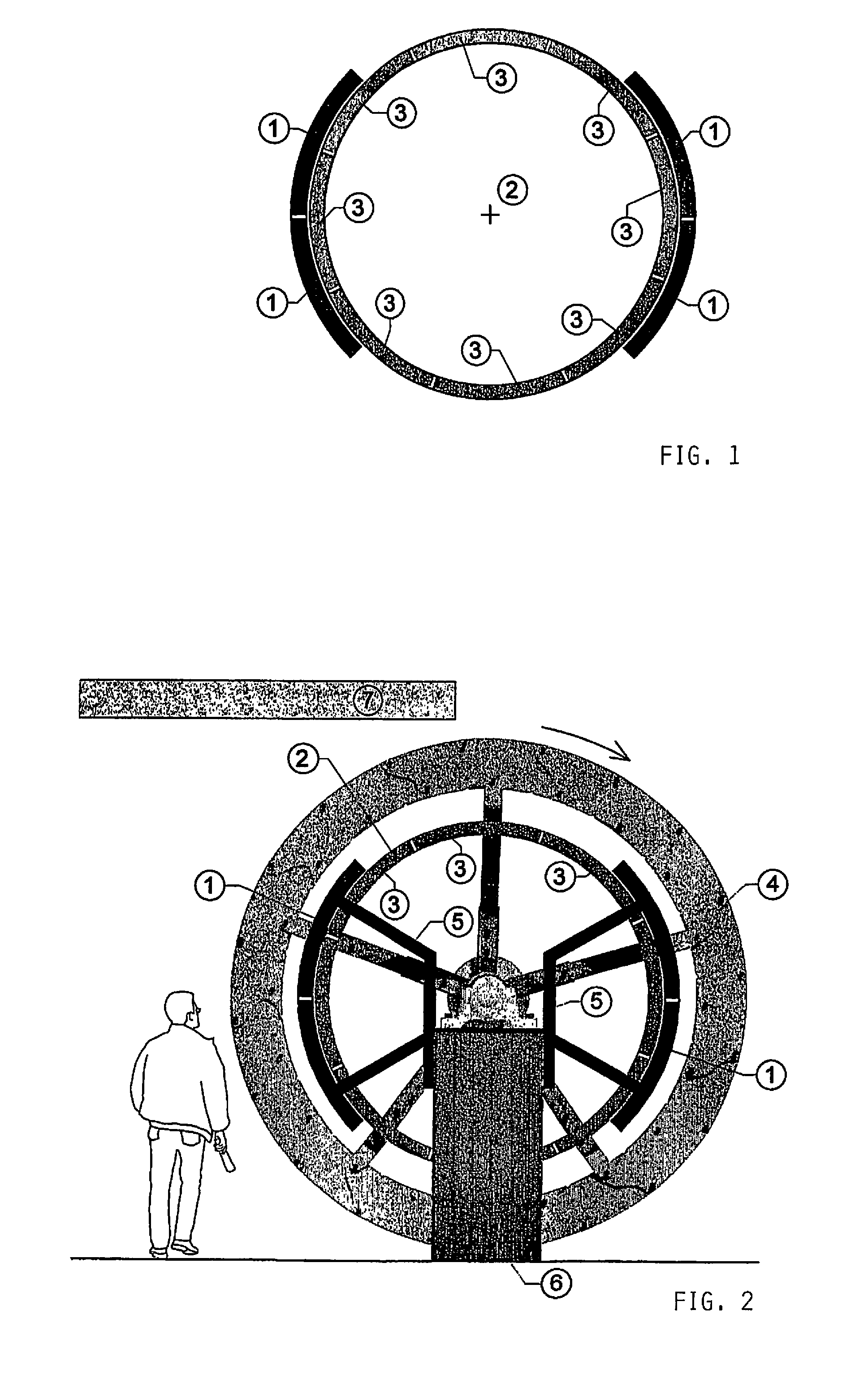
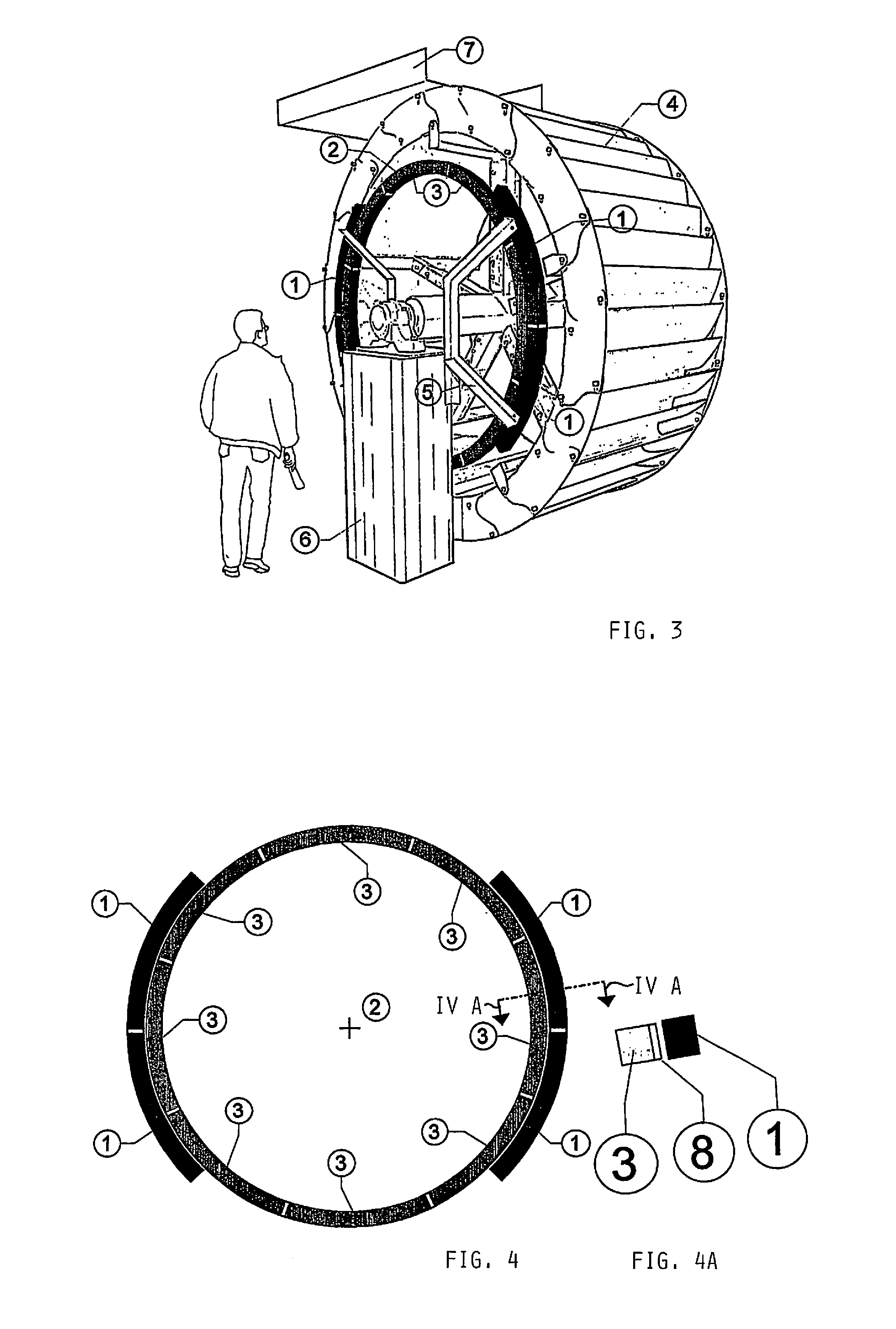
[0026]In the example embodiments, water wheels 4 are arranged, which are embodied as overshot water wheels 4 with an allocated water feed race or sluice 7 according to FIGS. 2, 3 and 8, and are arranged via or over a stationary foundation 6 in a known manner. Thereby in this case the water wheel 4 is constructed of individual wheel rim elements.

[0027]A ring generator is coupled with the water wheel 4, whereby the ring generator is formed by a rotor 2 as a ring element and is rigidly connected with the water wheel 4. In this regard, a connection is established with the arms of the water wheel body or directly on the formed ring.

[0028]This ring element as the rotor 2 is modularly assembled of individual segments 3, which are equipped or populated with corresponding permanent magnets 8. In this regard, high power magnets are used, as they are available, for example, under the tradename NEODYN magnets. The permanent magnets 8 in the example embodiments are arranged in the area of the fr...


PUM


Abstract

In a water wheel with an integrated electrical generator, a ring element for forming a rotor is rigidly concentrically connected with the water wheel. The ring element is assembled of modular individual segments with inserted permanent magnets. At least one corresponding partial ring as a stator is allocated to the rotor, whereby each partial ring carries electrical coils in correlation to the permanent magnets of the ring element of the rotor. The partial rings of the stator are stationarily mounted by holding elements on support struts of the water wheel.

Description

FIELD OF THE INVENTION[0001]The invention relates to a water wheel with an integrated generator, whereby the water wheel is drivable for current generation via allocated water paddles by streaming, jetted or free-falling flowing tail water.BACKGROUND INFORMATION[0002]As necessitated by the function, water wheels have a relatively low rotational speed with a high torque or rotational moment. Therefore it is typical for the generation of current, to connect a multi-stage mechanical gearing with a shaft stub of the water wheel, and to connect an output shaft of the gearing with a generator via a transmission.[0003]When there are changing water quantities, especially with an increase of the water quantity, the power and the torque are increased, so that the water wheel shaft and the gearing must take up relatively high peak torques.[0004]In practice, therefore, the design of the parts is carried out with a factor of three relative to the normal loading. Thereby, relatively heavy and exp...

Claims


Application Information

Patent Timeline
IPC IPC(8): F03B13/00H02P9/04F03D9/00
CPCF03B7/003F03B17/062H02K7/1823H02K21/24H02K41/03F05B2220/706F05B2220/7066F05B2220/7068H02K7/1869H02K2201/15Y02E10/223Y02E10/28Y02E10/20Y02E10/30F03B7/00F03B17/061
Inventor DREWS, HARTMUTH
Owner DREWS HARTMUTH
Learn More