High-frequency circuit in which high-frequency filter is parallel installed to integrated circuit

a high-frequency filter and integrated circuit technology, applied in the field of high-frequency circuits, can solve the problems of difficult to effectively use the mounting space for disposition of the saw filter, and the inability to acquire the original characteristics of the saw filter 103/b>, and achieve the effect of effective use of the mounting spa

Inactive Publication Date: 2013-04-16
ALPS ALPINE CO LTD
View PDF11 Cites 0 Cited by
  • Summary
  • Abstract
  • Description
  • Claims
  • Application Information

AI Technical Summary

Benefits of technology

[0010]The present invention is designed to solve the above-described problems, and an object of the invention is to provide a high-frequency circuit capable of acquiring the original transmission characteristics of a filter by preventing capacitive coupling between input and output terminals of the filter externally attached to the integrated circuit and effectively using a mounting space.
[0012]According to the above-mentioned configuration, while the first and second sides of the integrated circuit face each other, the first terminal is disposed on the first terminal of the integrated circuit forming a rectangular shape and the second terminal is disposed on the second side of the integrated circuit, and thus, a capacitive coupling circuit is not formed between the first and second terminals used as input and output terminals of the integrated circuit, and thereby it is possible to prevent deterioration of transmission characteristics of the high-frequency filter due to capacitive coupling of the input and output terminals of the high frequency filter. In addition, since a gap between the first and second terminals which is at least the same degree as that of the third side is acquired, terminal pitches can be formed to be appropriate for the scale of the high frequency filter, compared to a structure in which the input and output terminals of the integration circuit are disposed adjacently, and thereby it is possible to use the mounting space effectively.
[0015]According to the present invention, the original transmission characteristics of a filter by preventing capacitive coupling between input and output terminals of the filter externally attached to the integrated circuit can be acquired and the mounting space can be effectively used.

Problems solved by technology

However, in the conventional television tuner, since the output terminals 101b and 101c of the SAW filter 103 and the input terminals 104a and 104b thereof are disposed to be adjacent to each other on one side of the integrated circuit 108, the input and output sides of the SAW filter 103 are capacitively coupled, and thereby there is a problem that the original characteristics of the SAW filter 103 cannot be acquired.
In addition, since terminal pitches (for example 1.78 mm to 2.5 mm) of the SAW filter 103 are much larger than terminal pitches (for example, 0.5 mm to 0.65 mm) of the output terminals 101b and 101c and the input terminals 104a and 104b which are disposed on one side of the integrated circuit 108, there is a problem that it is difficult to effectively use a mounting space for disposition of the SAW filter 103 and the peripheral components.

Method used


Image

  • High-frequency circuit in which high-frequency filter is parallel installed to integrated circuit
  • High-frequency circuit in which high-frequency filter is parallel installed to integrated circuit
  • High-frequency circuit in which high-frequency filter is parallel installed to integrated circuit

Examples


Embodiment Construction

[0019]Hereinafter, an embodiment of the present invention will be described in detail with reference to the accompanying drawings.

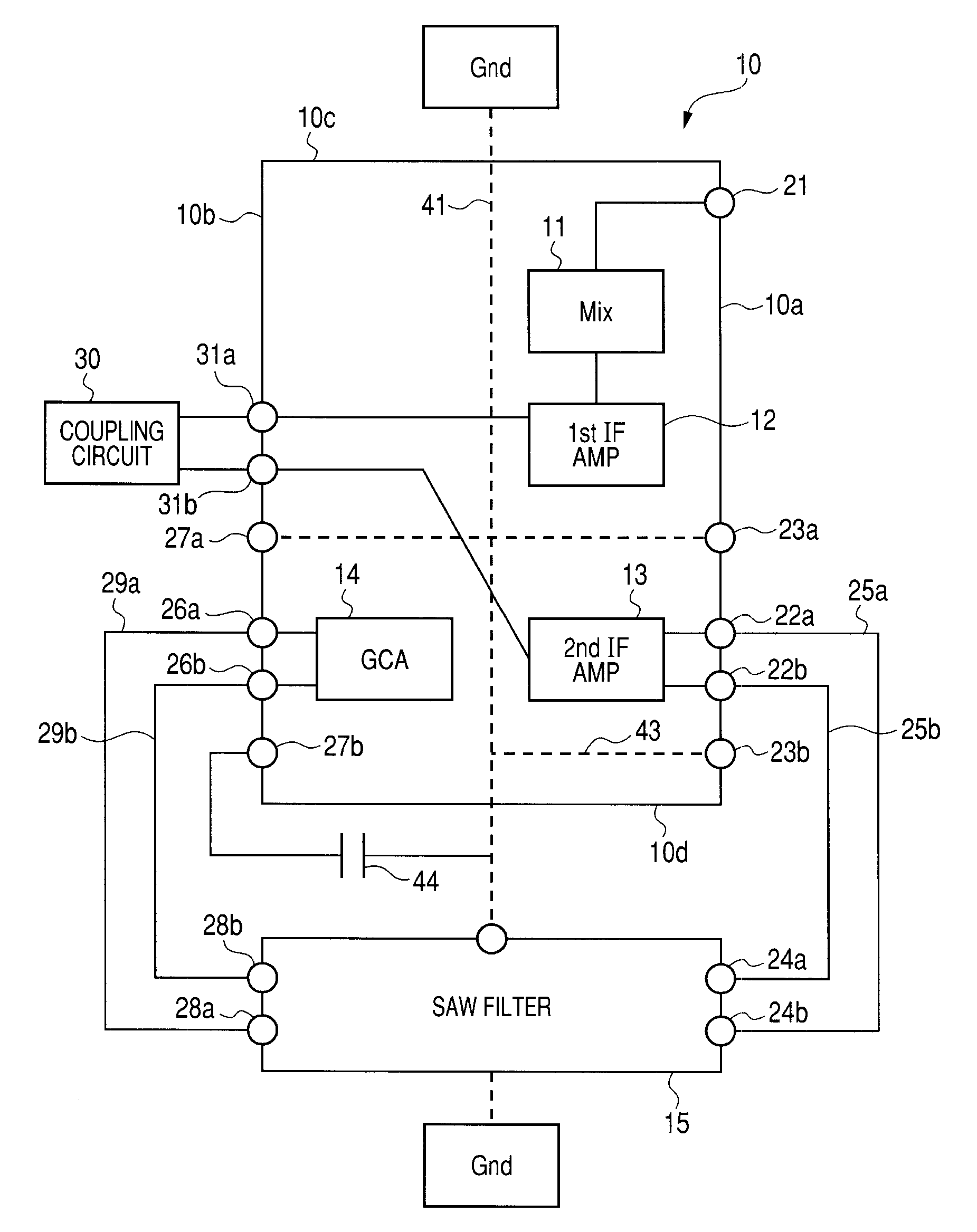
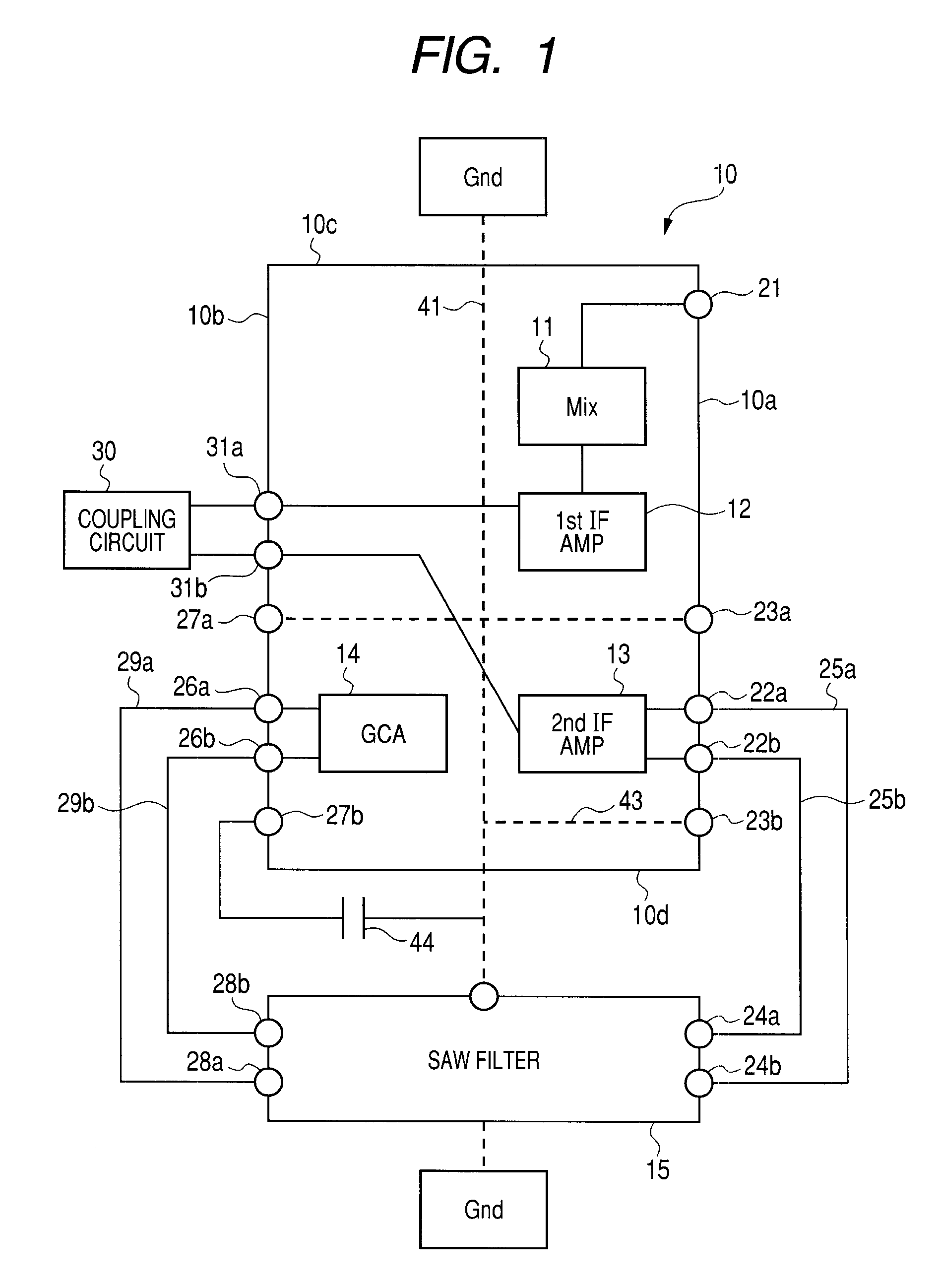
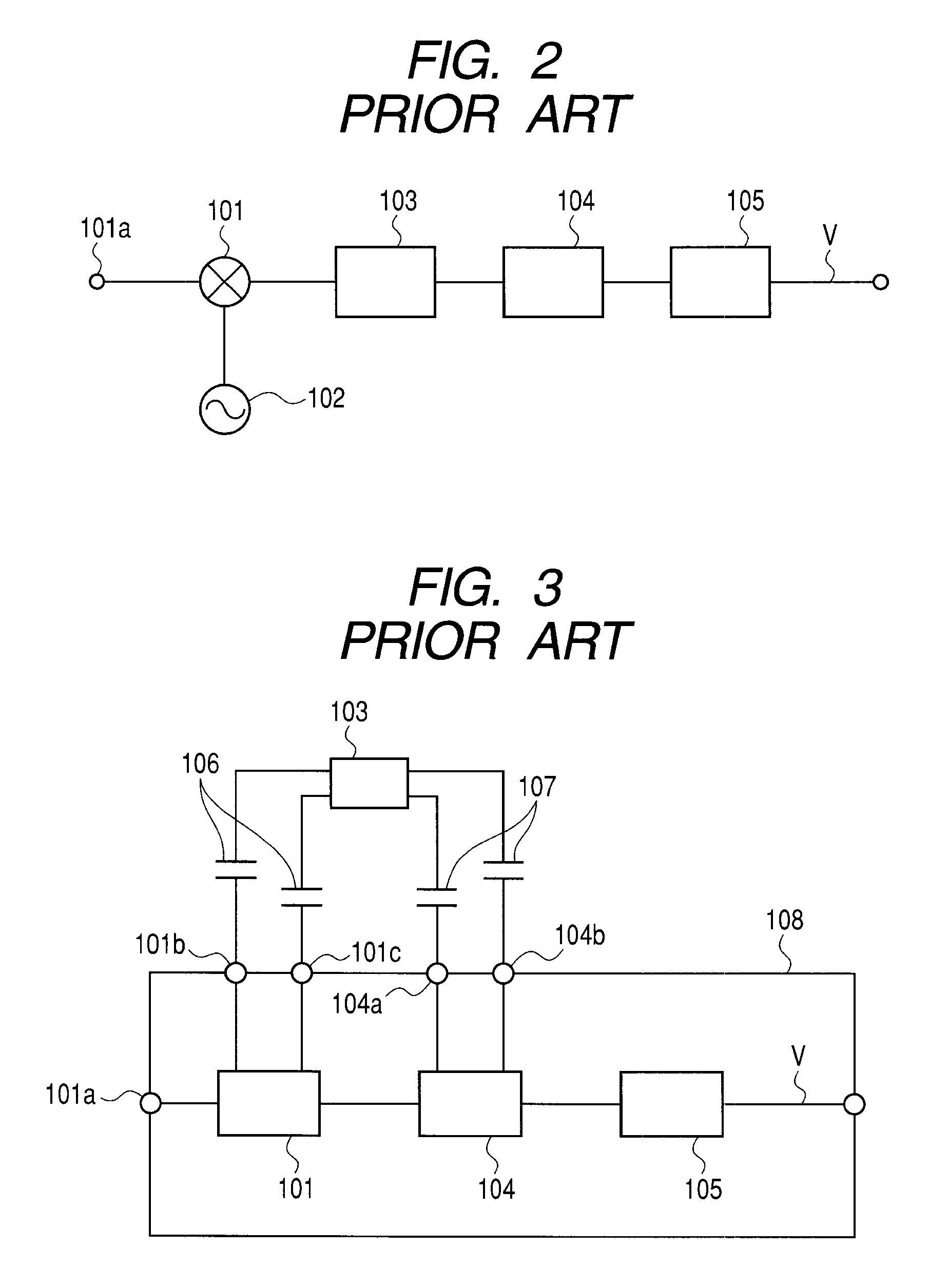
[0020]FIG. 1 is a diagram illustrating disposition of an integrated circuit of a television tuner according to an embodiment of the present invention and peripheral circuits thereof. Since the whole configuration of the television tuner is basically the same as shown in FIG. 2, a description thereof is omitted, here.

[0021]The integrated circuit 10 is disposed on a circuit substrate of the television tuner which is not shown in the figure. This integrated circuit 10 is in the shape of a rectangular and has a pair of left and right long sides 10a and 10b and a pair of upper and lower short sides 10c and 10d. In this embodiment, the pair of long sides 10a and 10b correspond to the first and second sides, and the pair of short sides 10c and 10d correspond to the fourth and third sides. When the integrated circuit 10 has a square shape, there is no difference ...


PUM


Abstract

The present invention provides a high-frequency circuit capable of acquiring the original transmission characteristics of a filter by preventing capacitive coupling between input and output terminals of the filter externally attached to the integrated circuit and effectively using a mounting space. The high-frequency circuit includes a rectangular integrated circuit 10 having two long sides 10a and 10b and two short sides 10c and 10d and a SAW filter 15, disposed to be adjacent to the short side 10d of the integrated circuit 10, having input terminals 24a and 24b disposed on the long side 10a side and output terminals 28a and 28b disposed on the other long side 10b side. IC output terminals 22a and 22b connected to input terminals 24a and 24b of the SAW filter 15 are disposed on a position of one long side 10a of the integrated circuit 10 on the SAW filter 15 side, and IC input terminals 26a and 26b connected to output terminals 28a and 28b of the SAW filter 15 are disposed on a position of the other long side 10b of the integrated circuit 10 on the SAW filter 15 side.

Description

BACKGROUND OF THE INVENTION[0001]1. Field of the Invention[0002]The present invention relates to a high-frequency circuit in which a high-frequency filter is parallel installed to an integrated circuit.[0003]2. Description of the Related Art[0004]Conventionally, a television tuner that has a mixer for converting an UHF band television signal or a VHF band television signal into an intermediate band television signal by converting the frequency of the UHF or VHF band television signal, an intermediate frequency band amplifier for amplifying the intermediate frequency band television signal, and a SAW filter, which includes a trap circuit for attenuating video and audio intermediate frequency signals of a channel adjacent to the intermediate frequency band, interposed between the mixer and the intermediate frequency amplifier has been proposed (for example, see JP-A-H11-69245 or JP-A-2003-318754).[0005]FIG. 2 is a diagram illustrating the configuration of a television tuner described ...

Claims


Application Information

Patent Timeline
Patent Type & Authority Patents(United States)
IPC IPC(8): H04B1/28H04B1/08H04N5/44
CPCH04N5/44H04N5/455H04N21/4263H03H9/17
Inventor YAMAMOTO, MASAKI
Owner ALPS ALPINE CO LTD
Why Eureka
Try Eureka