Therapeutic knee brace for a contrast therapy system

a contrast therapy and knee brace technology, applied in the field of knee braces, can solve the problems of knee impairment, affecting the ability to walk, crouch, climb and otherwise move freely, and being vulnerable to injury during activities, and achieve the effect of generating flexion

Inactive Publication Date: 2013-04-23
VITALWEAR
View PDF165 Cites 28 Cited by
  • Summary
  • Abstract
  • Description
  • Claims
  • Application Information

AI Technical Summary

Benefits of technology

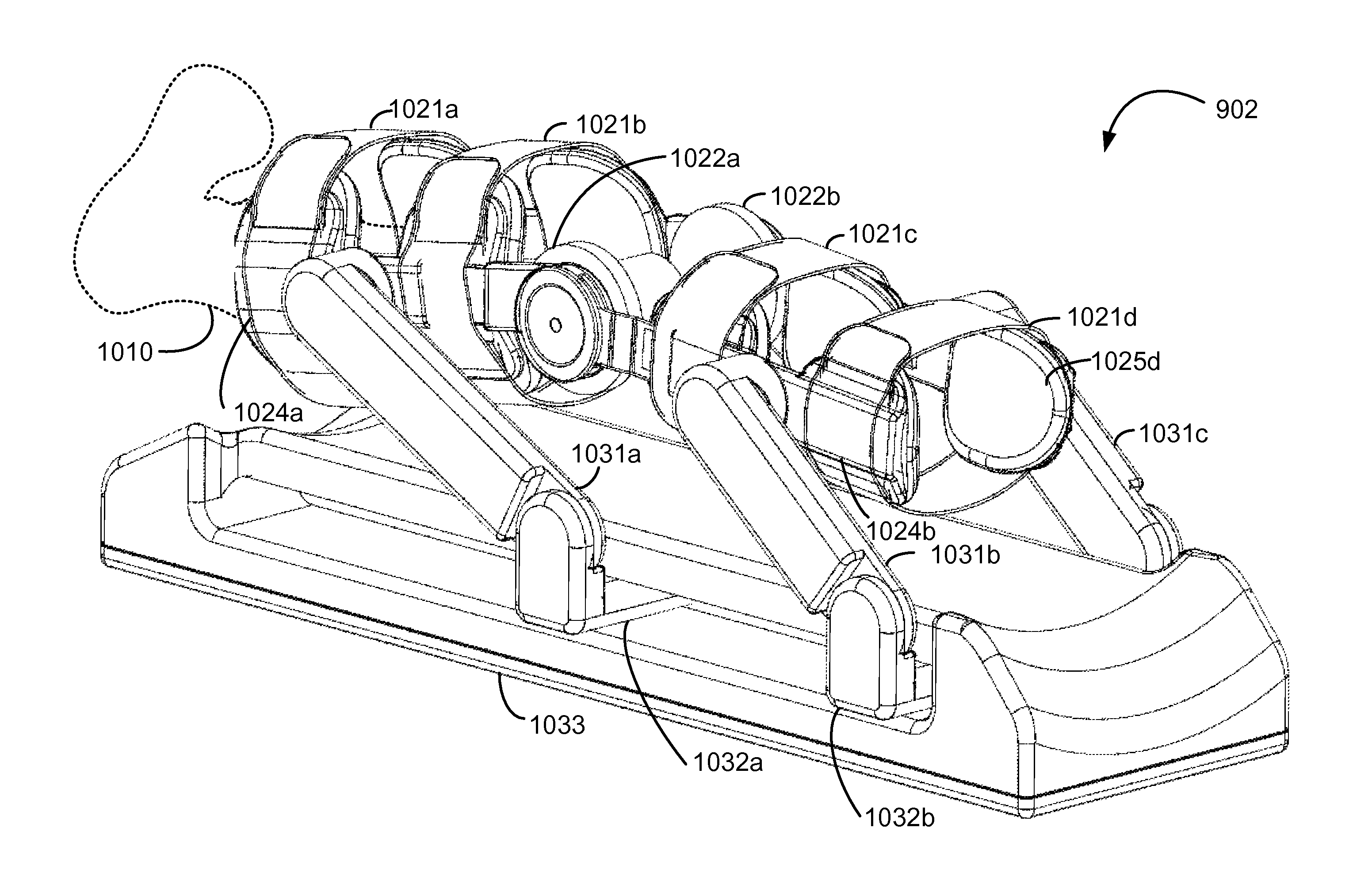
[0017]Additionally, the knee brace coupler is configured to selectively couple the therapeutic knee brace system with a specific CPM device, and the specific CPM device is configured to selectively couple with the therapeutic knee brace system. Such a selective ability to couple is important to ensure proper use and regulation of the knee brace in conjunction with the CPM device. Moreover, the knee brace coupler, when the knee brace is coupled with the CPM device, allows the CPM device to function, wherein the functioning includes the movement of the knee brace in passive motion, generating flexion along the brace joint when the knee brace is fully engaging the device.

Problems solved by technology

The knee is the largest joint in the body, and its exposed position makes it vulnerable to injury during activities.
Knee impairments affect a person's ability to walk, crouch, climb and otherwise move freely.
Additionally, knee impairments can be extremely debilitating and painful.
In most patients after extensive joint surgery, attempts at joint motion cause pain and as a result, the patient fails to move the joint.
This allows the tissue around the joint to become stiff and for scar tissue to form resulting in a joint which has limited range of motion and often may take months of physical therapy to recovery that motion.
For instance, implicated therapy sites are often sore upon entrance into therapy.
Removal of the knee brace prior to CPM therapy may be physically difficult, painful and time consuming.
If it is difficult for a therapy recipient to self apply a therapy, the opportunity to receive therapy may be diminished.
Furthermore, if therapies are complicated and / or uncomfortable, a therapy recipient is less likely to undergo the therapy, although it may be beneficial.

Method used


Image

  • Therapeutic knee brace for a contrast therapy system
  • Therapeutic knee brace for a contrast therapy system
  • Therapeutic knee brace for a contrast therapy system

Examples


Embodiment Construction

[0054]The present invention will now be described in detail with reference to several embodiments thereof as illustrated in the accompanying drawings. In the following description, numerous specific details are set forth in order to provide a thorough understanding of the present invention. It will be apparent, however, to one skilled in the art, that the present invention may be practiced without some or all of these specific details. In other instances, well known process steps and / or structures have not been described in detail in order to not unnecessarily obscure the present invention. The features and advantages of the present invention may be better understood with reference to the drawings and discussions that follow.

[0055]The present invention relates to therapeutic knee brace system including thermal contrast therapy systems and a method of providing contrast therapy. Additionally, the knee brace may be used in conjunction with a Continuous Passive Motion (CPM) device for ...


PUM


Abstract

The present invention relates to a therapeutic knee brace system including a leg brace for support, a retainer for securing the therapeutic knee brace system to a knee joint therapy site, a brace joint providing a limited range of flexion to the knee brace, and an active thermal exchange bladder coupled to a contrast therapy system for delivering a therapy fluid at a select temperature, pressure and rate. Thermal exchange bladder is removable, and the pressure may be constant or dynamic. The angle of flexion may be selected by the therapy recipient, and the range of flexion of the brace joint is configurable. The knee brace may communicate range and instant angle of flexion of the brace joint to a continuous passive motion (CPM) device, and communication may be mechanical, electronic or wireless. A knee brace coupler attaches to a CPM coupler on the CPM device to selectively couple the therapeutic knee brace system to the CPM device.

Description

CROSS REFERENCE TO RELATED APPLICATIONS[0001]This is a continuation-in-part of co-pending U.S. application Ser. No. 10 / 267,247 filed on Oct. 8, 2002, entitled “Contrast Therapy System and Method”, which is hereby fully incorporated by reference.BACKGROUND OF THE INVENTION[0002]The present invention relates to knee braces, and more particularly, to knee brace assemblies in conjunction with continuous passive motion (hereinafter “CPM”), which incorporate bladders, and which are adapted for use in a thermal or contrast therapy system, or medical thermal therapy system. The bladder element of the present invention enables the user to obtain a tightly controlled and consistent temperature or contrast therapy, along with support, pressure and / or compression therapy. Additionally, the knee brace includes an intelligent joint, capable of being configured to a range of flexion and transmitting the instant angle and the configured range of flexion to the continuous passive motion device.[0003...

Claims


Application Information

Patent Timeline
Patent Type & Authority Patents(United States)
IPC IPC(8): A61F7/00A61H1/00
CPCA61F7/02A61F5/0123A61F7/0085A61F2007/0018A61F2007/0054A61F2007/0056A61F2007/0296
Inventor EDELMAN, HOWARDLIU, DAQING
Owner VITALWEAR
Why Eureka
Try Eureka