Supercharge Your Innovation With Domain-Expert AI Agents!

Integrated optical module

a technology of optical modules and optical components, applied in the field of integrated optical modules, can solve the problems of occupying precious space, negatively affecting the performance of the ofn device, and inefficient merely placing separate optical components that are suitable for each individual mode of operation in a single device, and achieve the effect of wide scanning area

Active Publication Date: 2013-04-23
LITE ON SINGAPORE PTE LTD
View PDF11 Cites 0 Cited by
  • Summary
  • Abstract
  • Description
  • Claims
  • Application Information

AI Technical Summary

Benefits of technology

The patent describes how to create an optical package that can shine light in different ways to illuminate a wide area. This allows for better projection patterns and can be adapted to fit in a small space.

Problems solved by technology

However, OFN devices of conventional design often employ separately arranged illumination and imaging optical components around the sensing surface thereof, which occupy precious space.
Also, a separated optical arrangement tends to generate less uniformed illumination output across a wide area of the sensing surface, which may negatively affect the performance of the OFN device.
Therefore, merely placing separate optical components that are suitable for each individual mode of operation in a single device is inefficient from both a cost effectiveness aspect and a space utilization aspect.

Method used


Image

  • Integrated optical module
  • Integrated optical module
  • Integrated optical module

Examples


Embodiment Construction

[0020]The instant disclosure will be described more specifically with reference to the following embodiments. It is to be noted that the following descriptions of preferred embodiments are provided herein for purpose of illustration and description. It is not intended to be exhaustive or limiting to the precise form disclosed.

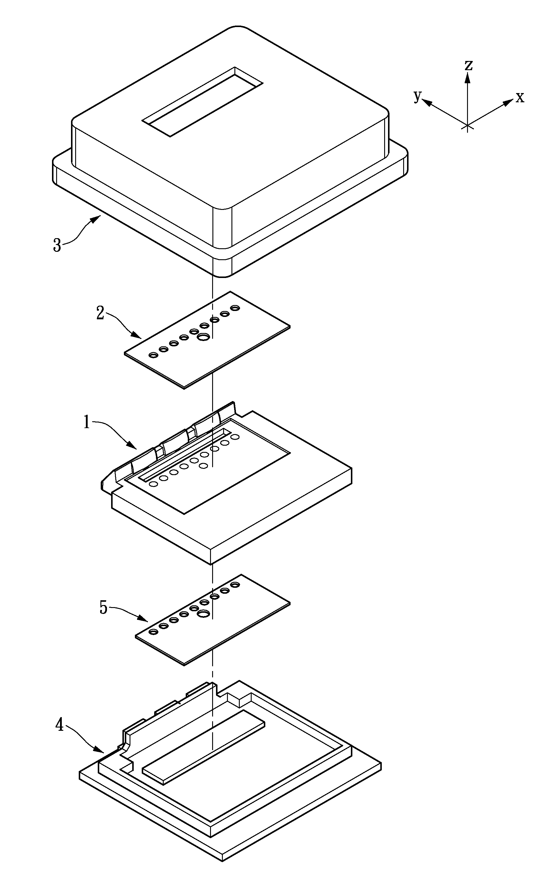
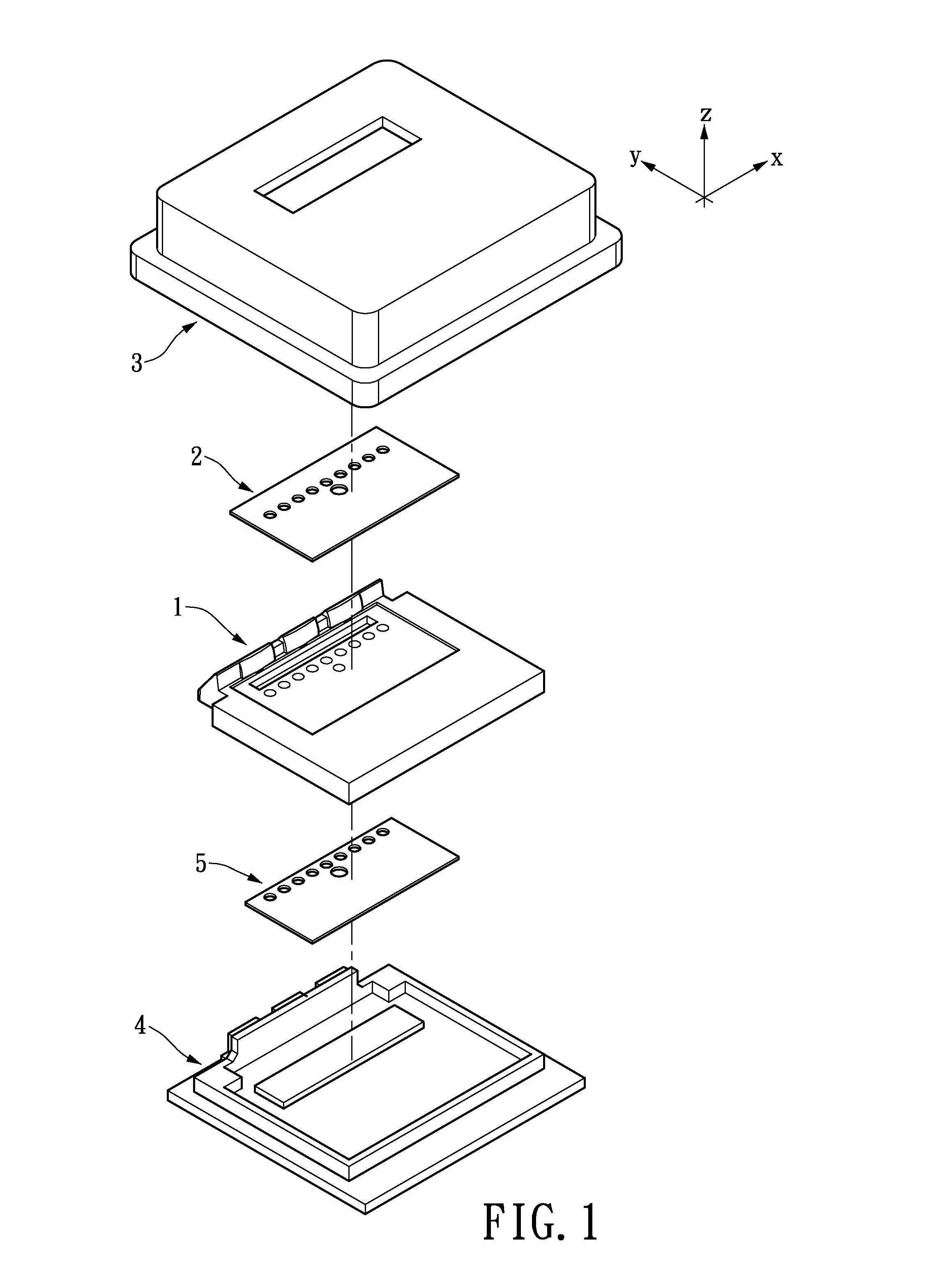
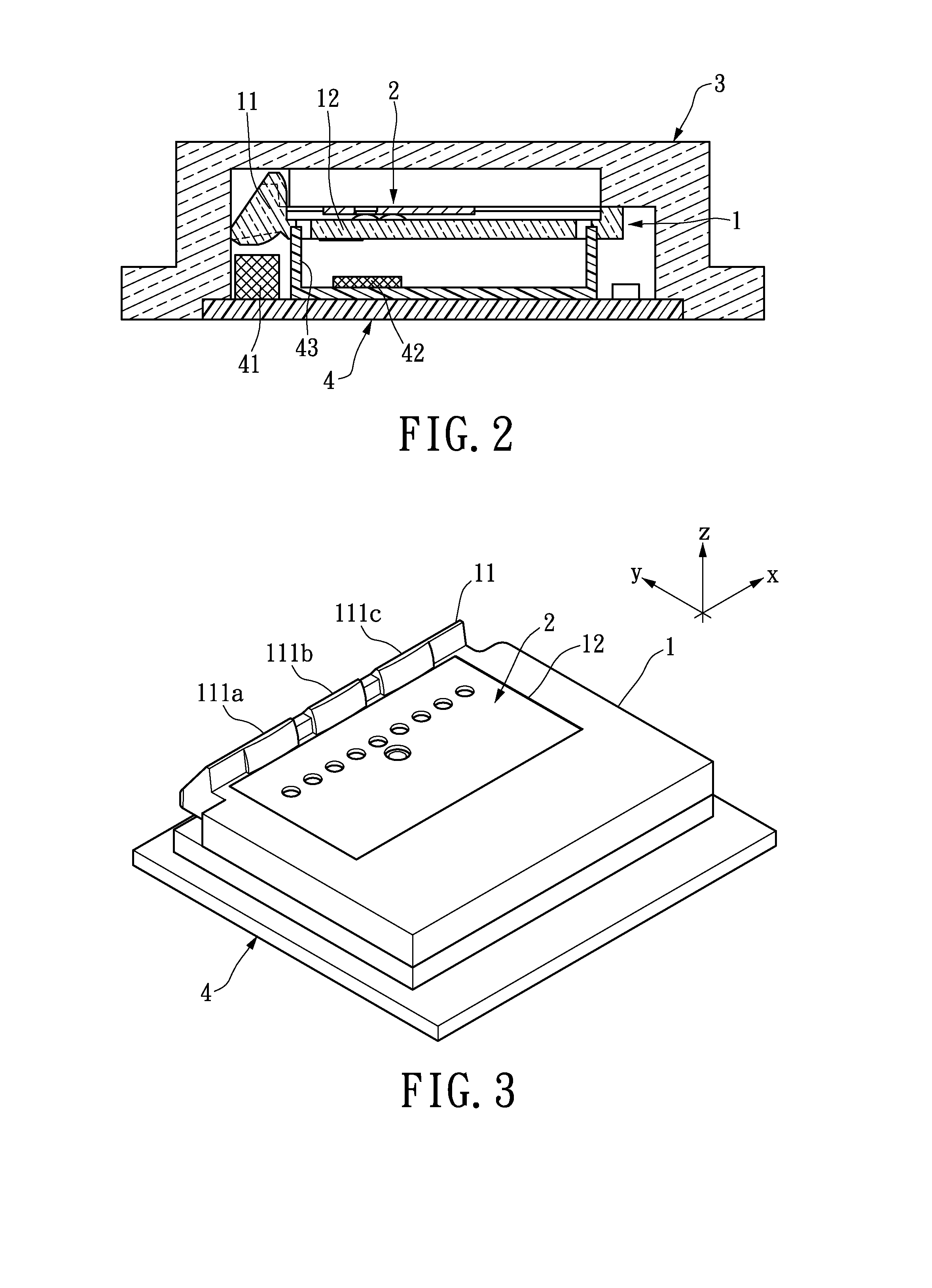
[0021]FIG. 1 depicts an exploded overview of an optical finger sensing device utilizing an integrated optical module in accordance with the instant disclosure. Particularly, the optical module discussed in the instant exemplary embodiment, together with the corresponding component arrangement of the optical finger sensing device, enable capabilities in both finger navigation and fingerprint recognition operations. From bottom to top, the sensor package of the exemplary finger sensing device generally includes an electronic module 3 having a light source unit and a light detector unit disposed on a substrate, an integrated optical module having an illuminating p...


PUM


Abstract

The instant disclosure relates to an integrated optic module for adapting in a finger sensing apparatus. The integrated optic module comprises an illumination portion including a light guiding array arranged to direct incident light from the electronic module toward the window module at a predetermined angle of incidence and an imaging portion having an imaging lens array arranged thereon to direct reflected light from the window module toward the electronic module for photo imaging. The micro-lens array includes an elongated recognition unit having a row axis substantially normal toward the light guiding array and a navigation unit adjoining the recognition unit and offsetting the row axis thereof. The optic module mediates a window module and an electronic module to provide both finger navigation and fingerprint recognition capabilities.

Description

BACKGROUND OF THE INVENTION[0001]1. Field of the Invention[0002]The instant disclosure relates generally to an integrated optical module adaptable in a finger sensing device, and pertains particularly to an integrated optical module adaptable in a fingerprint imaging device for finger navigation and biometric scanning purposes.[0003]2. Description of Related Art[0004]While modern devices share a common design trend toward miniaturization in physical size, their functionality has grown tremendously sophisticated and diversified. As a result, conventional human interface devices (HID), such as mouse and keyboard, are often rendered inadequate when adapted . Constant efforts have been devoted to finding a precise and intuitive miniaturized control interface capable of enabling intimate human-machine interaction. Particularly, as these personalized electronic devices are deeply integrated into modern daily life, they are expected to be operated under a variety of conditions. Therefore, ...

Claims


Application Information

Patent Timeline
Patent Type & Authority Patents(United States)
IPC IPC(8): G03B29/00
CPCG06K9/00046G06F3/03547G06F3/0317G06F2203/0338G06V40/1324
Inventor SAXENA, KULDEEP KUMAR
Owner LITE ON SINGAPORE PTE LTD
Features
  • R&D
  • Intellectual Property
  • Life Sciences
  • Materials
  • Tech Scout
  • Unparalleled Data Quality
  • Higher Quality Content
  • 60% Fewer Hallucinations
Learn More