Eureka AIR delivers breakthrough ideas for toughest innovation challenges, trusted by R&D personnel around the world.

Apparatus and method for allocating downlink control channel

a control channel and control channel technology, applied in the direction of error prevention, digital transmission, wireless communication, etc., can solve the problems of accelerating the exhaustion of available frequency resources in a frequency band lower than 3 ghz, affecting the efficiency of resource utilization, and interference between neighboring cells or sectors in the boundary of a cell or sector, etc., to achieve the flexibility of transmission of a-map, increase the efficiency of resource utilization, and increase the decoding performance of the terminal located

Inactive Publication Date: 2013-04-23
LG ELECTRONICS INC
View PDF2 Cites 6 Cited by
  • Summary
  • Abstract
  • Description
  • Claims
  • Application Information

AI Technical Summary

Benefits of technology

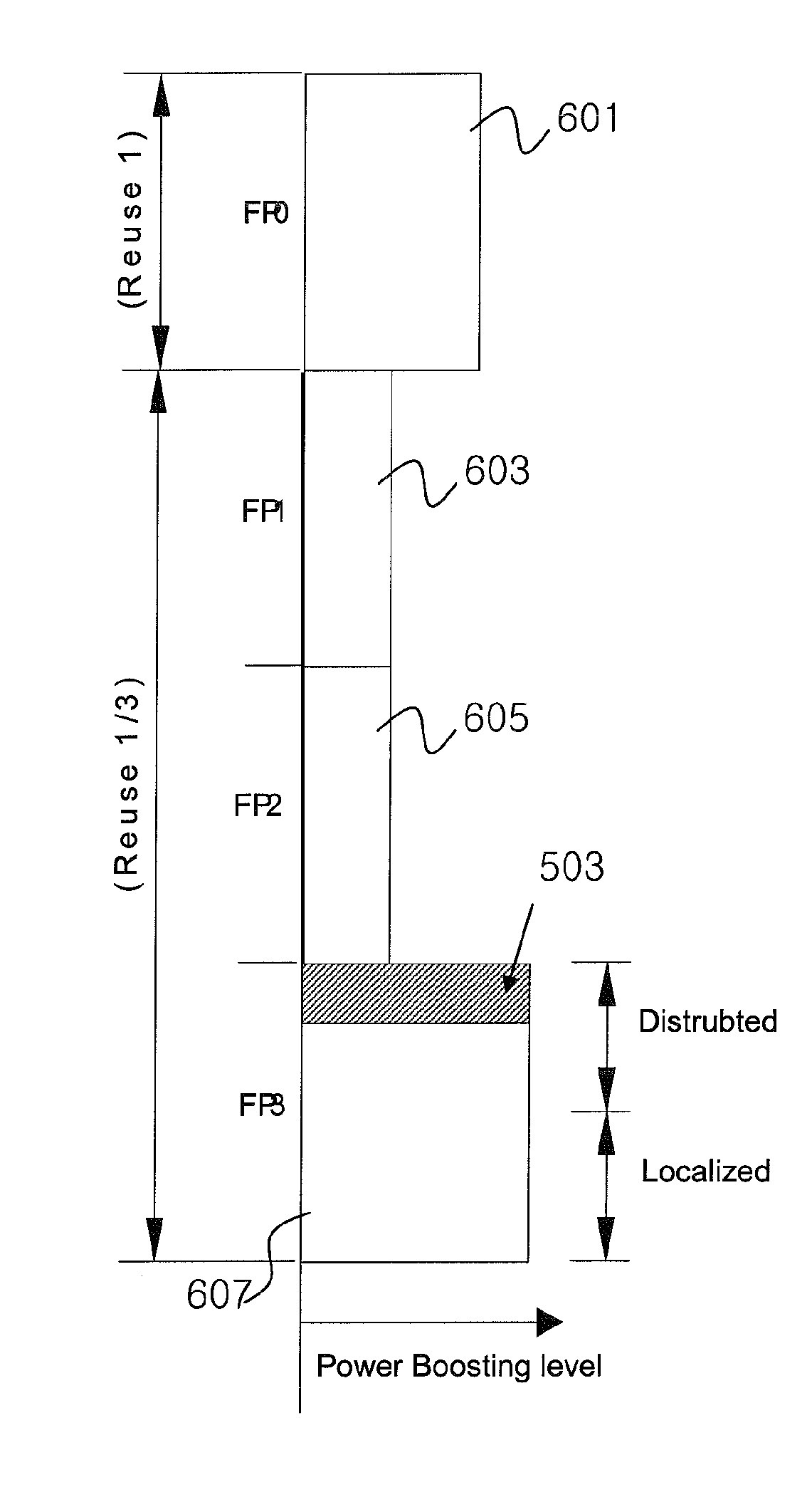
[0022]According to exemplary embodiments of the present invention, in the FFR system in which the frequency reuse factor 1 and 3 (or 1 / 3) areas coexist, the control information channel common to every user is configured as a non user specific (NUS) A-MAP and transmitted to a power boosted area of Reuse 3, thus increasing the efficiency in using resources, and because the power level is higher than that of other areas, the NUS A-MAP decoding performance of the terminal located at the cell edge can be increased.
[0023]In addition, when the position of the NUS A-MAP is fixed in the system, the base station does not need to broadcast information regarding the position of the NUS A-MAP to a terminal. In this respect, however, when the position of the NUS A-MAP is transmitted through an SFH, the base station can transmit the NUS A-MAP to a location desired by the base station, so flexibility of the transmission of A-MAP can be increased.

Problems solved by technology

Currently, the explosive increase in demand for radiowave resources, as well as the advancement of a communication environment, accelerates the exhaustion of available frequency resources in a frequency band lower than 3 GHz.
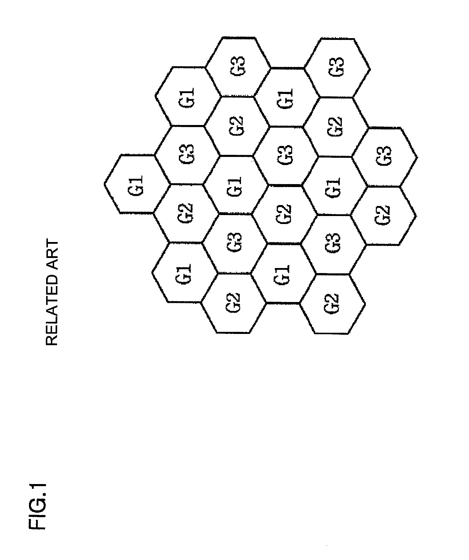
The frequency reuse factor K is a value indicating how many cells or sectors the same frequency is reused in, and as the frequency reuse rate increases, the distance between cells or sectors using the same frequency is longer, reducing interference caused by using the same frequency, which, however, accompanies degradation of efficiency in terms of resource utilization.
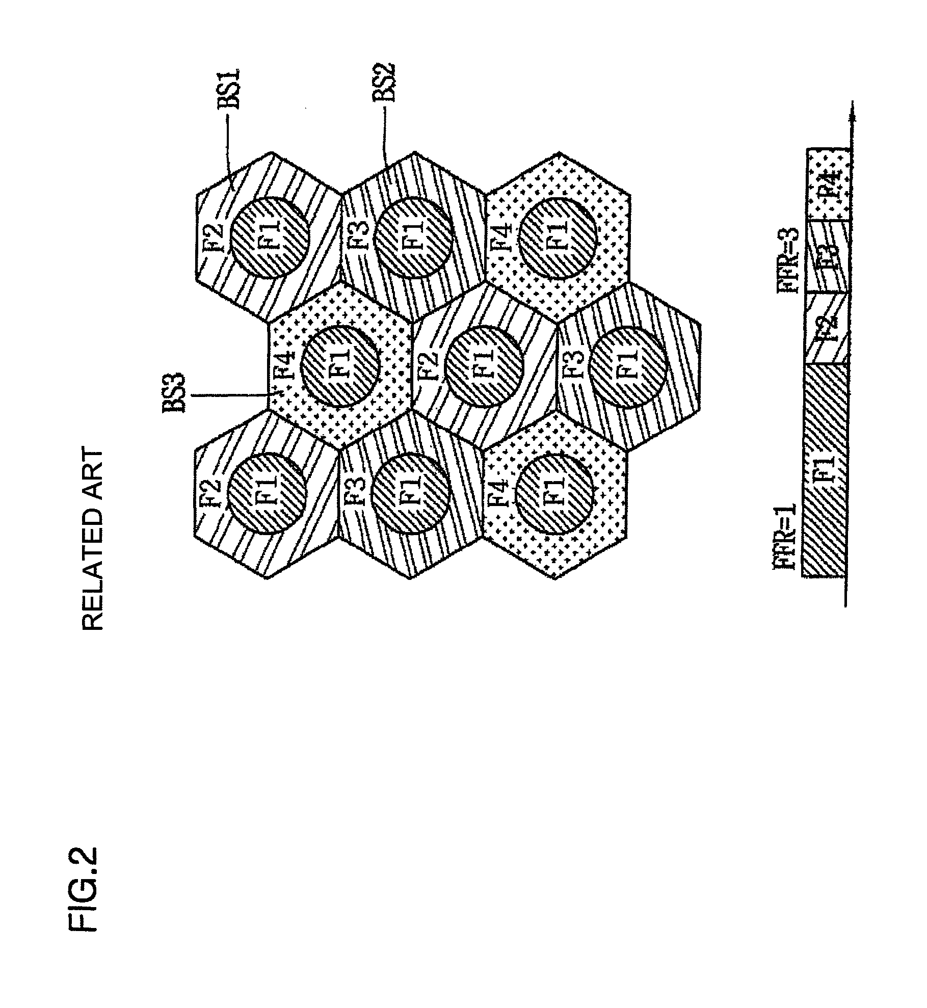
Thus, in order to enhance efficiency of frequency resource utilization, it is preferred to use such that the frequency reuse rate is close to 1, but when the frequency reuse rate is 1, a problem arises in that interference between neighboring cells or sectors occurs in the boundary of a cell or sector.
Namely, the terminal located at the central area is not distant from a base station, degradation of receive sensitivity of a signal component due to a path attenuation is low, but relatively distant from a neighboring interference base station, greatly affected by the path attenuation, resulting in a decrease in the influence of the same channel interference.
In this case, overhead of control channels with respect to data can be advantageously distributed to the respective channels, but because common non-user specific control information (NUSCI) must be included in every partition, overhead is generated, and particular areas (i.e., areas which are not power-boosted in a Reuse 3 area) has a weak power strength, possibly generating a decoding error in a terminal located at a cell edge.
Also, a problem arises in that processing overhead of the terminal that decodes the non-user specific MAP with respect to every partition increases.
In addition, when the MAP area is allocated only to one partition among the plurality of frequency partitions, repetition of the common control information can be advantageously reduced, but causing a problem in that because the MAP area is positioned only at the one partition, control overhead of the partition where the corresponding MAP area is positioned increases.

Method used


Image

  • Apparatus and method for allocating downlink control channel
  • Apparatus and method for allocating downlink control channel
  • Apparatus and method for allocating downlink control channel

Examples


Embodiment Construction

[0035]Exemplary embodiments of the present invention will now be described in detail with reference to the accompanying drawings. The same reference numerals will be used throughout to designate the same or like components and a repeated description will be omitted. In describing the present invention, if a detailed explanation for a related known function or construction is considered to unnecessarily divert the gist of the present invention, such explanation will be omitted but would be understood by those skilled in the art. In the drawings, the shapes and dimensions may be exaggerated for clarity, and the same reference numerals will be used throughout to designate the same or like components. The accompanying drawings, which are given by illustration only, and thus are not imitative of the present invention.

[0036]The terminal according to an exemplary embodiment of the present invention may also be referred to as subscriber station (SS), user equipment (UE), mobile equipment (M...


PUM


Abstract

A method for allocating a downlink control channel in a fractional frequency reuse (FFR) system, includes: dividing a service frequency band of the system into a plurality of frequency partitions including a first frequency partition corresponding to a first frequency reuse factor, a second frequency partition corresponding Kth frequency reuse factor, and a third frequency partition; setting a transmission power level for each of the plurality of divided frequency partitions; allocating a downlink common control channel including non-user specific (NUS) control information common to every user to a particular frequency partition corresponding to the highest transmission power level among the set transmission power levels; and transmitting the NUS control information through the particular frequency partition.

Description

CROSS-REFERENCE[0001]The present application claims priority benefit to the following applications, which contents are all incorporated by reference herein: U.S. Provisional Application No. 61 / 222,938 filed on Jul. 3, 2009.BACKGROUND OF THE INVENTION[0002]1. Field of the Invention[0003]The present invention relates to a structure of a downlink control channel and method for allocating a downlink control channel in a broadband wireless access system and, more particularly, to a method and apparatus for allocating a downlink control channel in a system using a fractional frequency reuse (FFR).[0004]2. Description of the Related Art[0005]Currently, the explosive increase in demand for radiowave resources, as well as the advancement of a communication environment, accelerates the exhaustion of available frequency resources in a frequency band lower than 3 GHz.[0006]In an effort to overcome the exhaustion of frequency resources, a frequency reuse technology has been proposed.[0007]In a c...

Claims


Application Information

Patent Timeline
Patent Type & Authority Patents(United States)
IPC IPC(8): H04B7/00
CPCH04W72/082H04L1/1812H04W72/042H04W72/0453H04W72/541H04W72/23
Inventor KIM, JEONGKIKIM, SUNAMKWAK, JINSAMYUK, YOUNGSOOCHOI, JINSOO
Owner LG ELECTRONICS INC
Why Eureka
Eureka Blog
Learn More