
Method for reinforcement of concreted plates in the region of support elements

a technology of support elements and concreted plates, which is applied in the direction of structural elements, building repairs, building components, etc., can solve the problems of unoptimized force transmission and the need for both sides of the concreted plate to be reinforced, and achieve the effect of large absorption of forces and simple handling

Inactive Publication Date: 2013-04-30
F J ASCHWANDEN AG
View PDF38 Cites 3 Cited by
  • Summary
  • Abstract
  • Description
  • Claims
  • Application Information

AI Technical Summary

Benefits of technology

This method achieves optimal reinforcement with minimal time and effort, providing precise force transmission and allowing for easy retensioning, using corrosion-resistant carbon-fiber reinforced synthetic materials for efficient force absorption.

Problems solved by technology

This type of reinforcements for concreted plates in the region of support elements has the drawback that the concreted plate to be reinforced must be accessible on both sides.
These tension rods have the disadvantage, however, that in many cases the force transmission is not optimal since the points of load incidence cannot be precisely established.

Method used


Image

  • Method for reinforcement of concreted plates in the region of support elements
  • Method for reinforcement of concreted plates in the region of support elements
  • Method for reinforcement of concreted plates in the region of support elements

Examples


Embodiment Construction

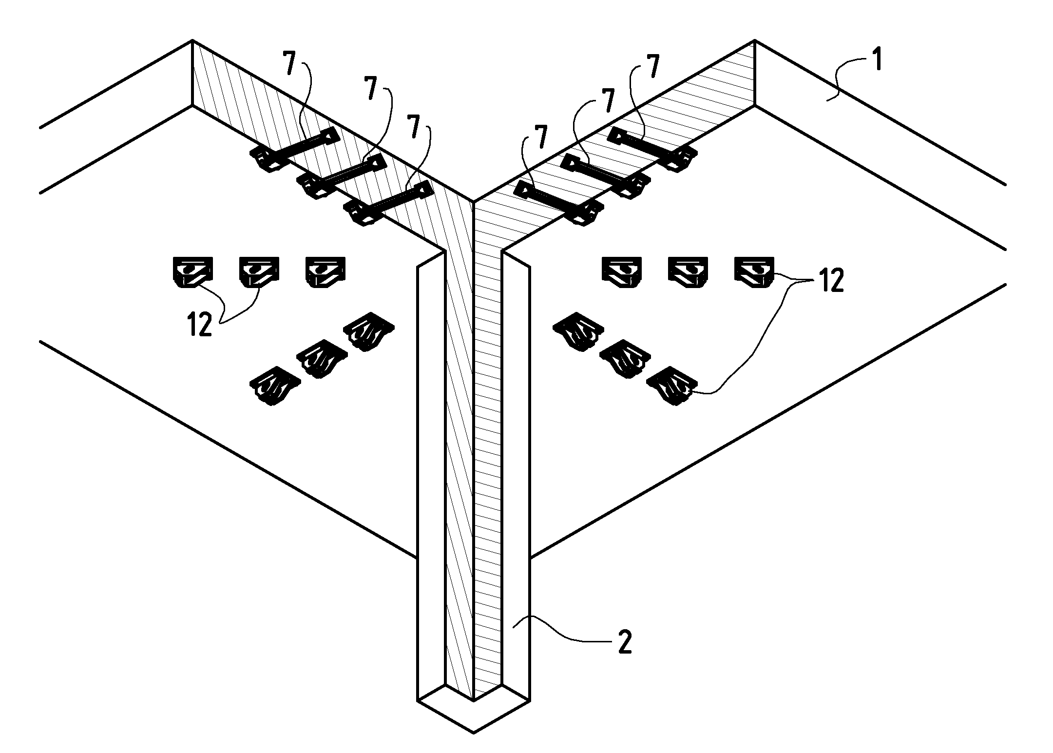
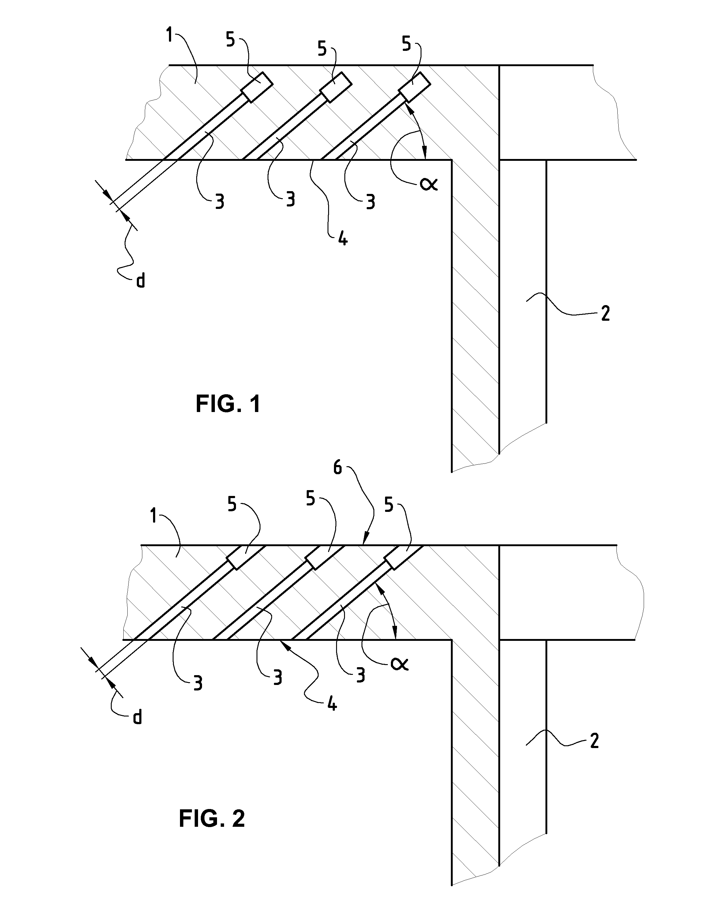
[0028]Visible in FIG. 1 is a concreted plate 1, which is supported by a support element 2. This support element 2 can be a supporting member, for example. It can also be a load-bearing wall or the like, however. Of course the concreted plate 1 is reinforced in the region of the support element 2 in a known way (not shown) with corresponding concrete reinforcements, for instance by means of so-called reinforcing cages.

[0029]Such a concreted plate 1 can be additionally reinforced in the region of the support elements 2. According to the method of the present invention, bores 3 are made in the concreted plate 1. These bores 3 are disposed in a way inclined from the pressure-side surface 4 of the concreted plate 1 at an angle α toward the corresponding support element 2. The angle α can thereby be about 30° to 60°. These bores 3 have a diameter d. The end region 5 of the respective bore 3 remote from the pressure-side surface 4 is drilled out to a diameter greater than the diameter d. T...


PUM


Abstract

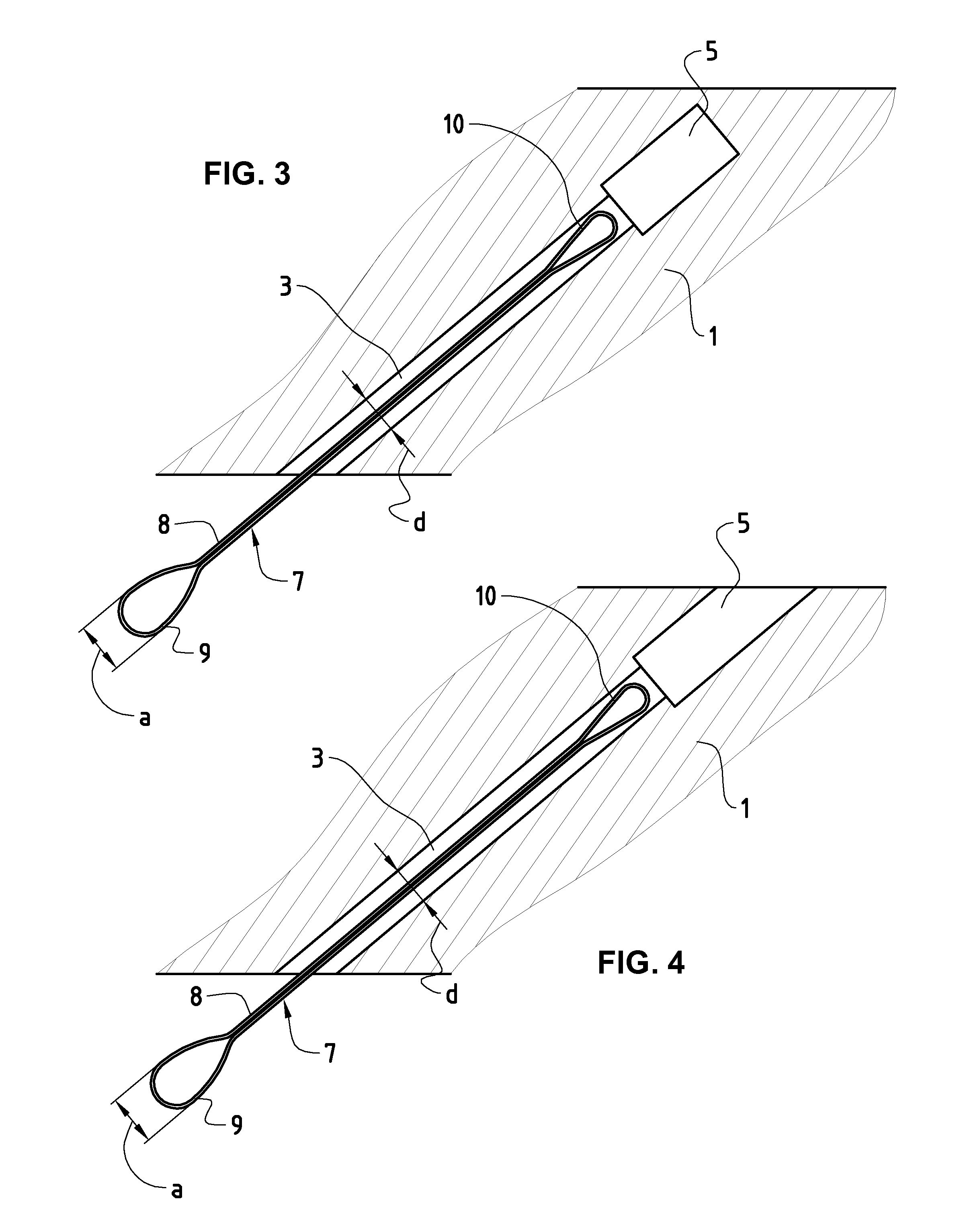
A method is provided for reinforcing concreted plates in the region of support elements with reinforcement elements, which are each composed of a longitudinally stable, bendable, strap-like base body with two loops. A bore is made in the concreted plate for each reinforcement element. The end region of the bore remote from the pressure-side surface of the concreted plate is drilled out and the one loop of the reinforcement element is pressed together and is led through the bore until this loop has reached the drilled-out hole and expands. The bore is filled with a mortar-type mass. The other loop of the reinforcement element is fixed with an anchor head, which supports itself on the pressure-side surface of the concreted plate.

Description

BACKGROUND AND SUMMARY[0001]The present invention relates to a method for reinforcement of concreted plates in the region of support elements, in particular supporting members and load-bearing walls, using reinforcement elements, which are each composed of a longitudinally stable, bendable, strap-like base body, both end regions of which are designed as loop, which loops have in the slack state a width a and which are inserted into the concreted plates to be reinforced.[0002]In the region of support elements, in particular supporting members or load-bearing walls, the concreted plates, which can be designed as floor plates on which support elements come to stand or as ceiling plates which are supported by support elements, are reinforced in a targeted way through concrete reinforcements or other strengthening elements. Known are, for instance, reinforcing cages which are concreted in the plate to be set in concrete. All these reinforcement elements have the aim of being able to tran...

Claims


Application Information

Patent Timeline
Patent Type & Authority Patents(United States)
IPC IPC(8): E04B1/00
CPCE04G23/0237E04G23/024
Inventor KELLER, THOMAS
Owner F J ASCHWANDEN AG
Learn More