Structure for cooling heating element

a technology for heating elements and structures, applied in the control arrangement of battery/fuel cell, electrochemical generators, lighting and heating apparatus, etc., can solve the problems of liquid overflow and entering the battery, battery damage, battery damage,

Active Publication Date: 2013-04-30
HIGHLY MARELLI JAPAN CORPORATION
View PDF8 Cites 25 Cited by
  • Summary
  • Abstract
  • Description
  • Claims
  • Application Information

AI Technical Summary

Benefits of technology

[0010]Therefore, the liquid entered the intake duct from the passenger compartment is surely brought into the water reserving portion of the intake duct, and then it is discharged through the discharge hole toward the wall, where the liquid falls down along the wall. This ensures the liquid to be prevented from entering the air passageway of the heat element box. Accordingly, the heat element can be prevented from damages due to the liquid.
[0014]Therefore, this can prevent the discharge hole from being covered by the wall even when the expansion portion contacts with the wall.
[0018]Therefore, the discharged liquid on the bottom surface of the intake duct is separated from the projected portion to be forcibly fallen down near the wall. This ensures the liquid to be prevented from entering the heat element.
[0020]Therefore, the battery can be cooled down without invasion of the liquid from the passenger compartment.
[0022]Therefore, the liquid fallen along the wall can be surely brought in the inner space formed by the spare wheel recess portion, which can prevent the liquid from being accumulated on a floor where the heat element is placed.

Problems solved by technology

However, in the above known conventional a structure for cooling a heat element, there are problems in that, although the water reserving portion of the air duct can accumulate the entering liquid such as water and splash and avoid its invasion to the battery, the liquid overflows and enter the battery when large volume of the liquid is inhaled into the air duct.
This causes the battery to be damaged.
This also causes the battery to be damaged.

Method used


Image

  • Structure for cooling heating element
  • Structure for cooling heating element
  • Structure for cooling heating element

Examples


Embodiment Construction

[0032]Throughout the following detailed description, similar reference characters and numbers refer to similar elements in all figures of the drawings, and their descriptions are omitted for eliminating duplication.

[0033]In a first preferred embodiment according to the present invention, a structure for cooling a heating element is applied to an electric vehicle, and the heating element is a battery that is capable of supplying an electric motor and other electric devices with electric power.

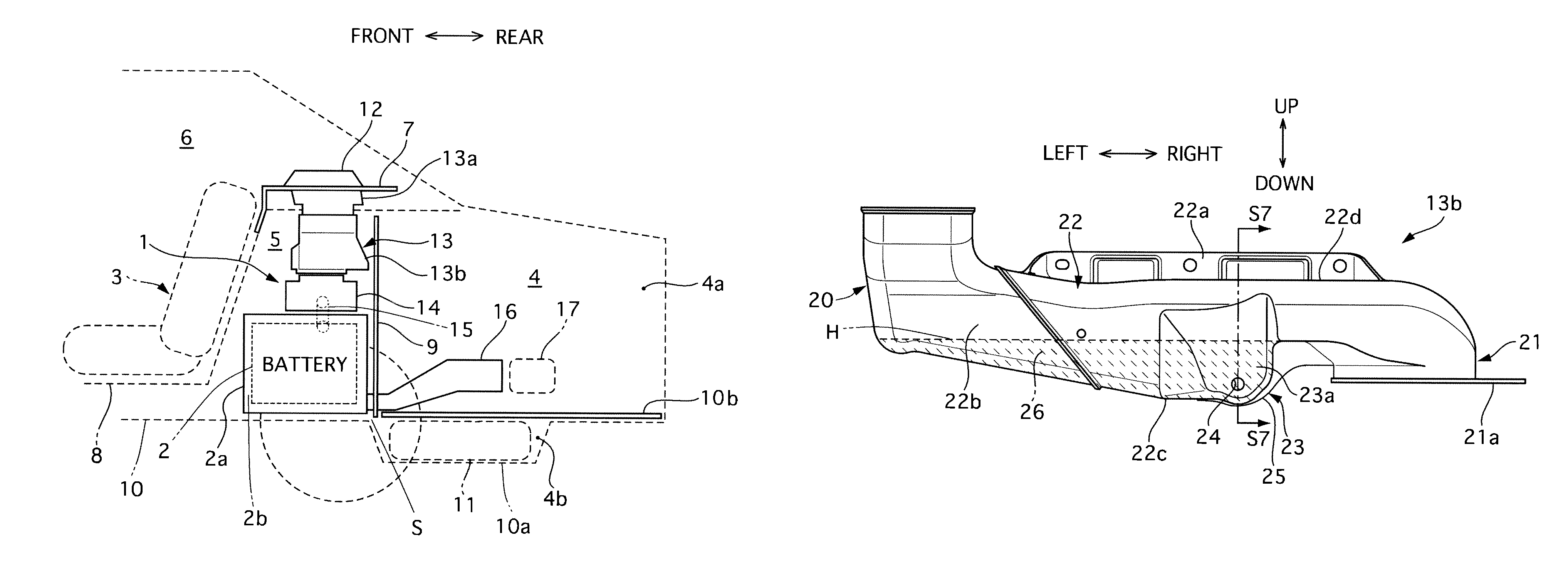
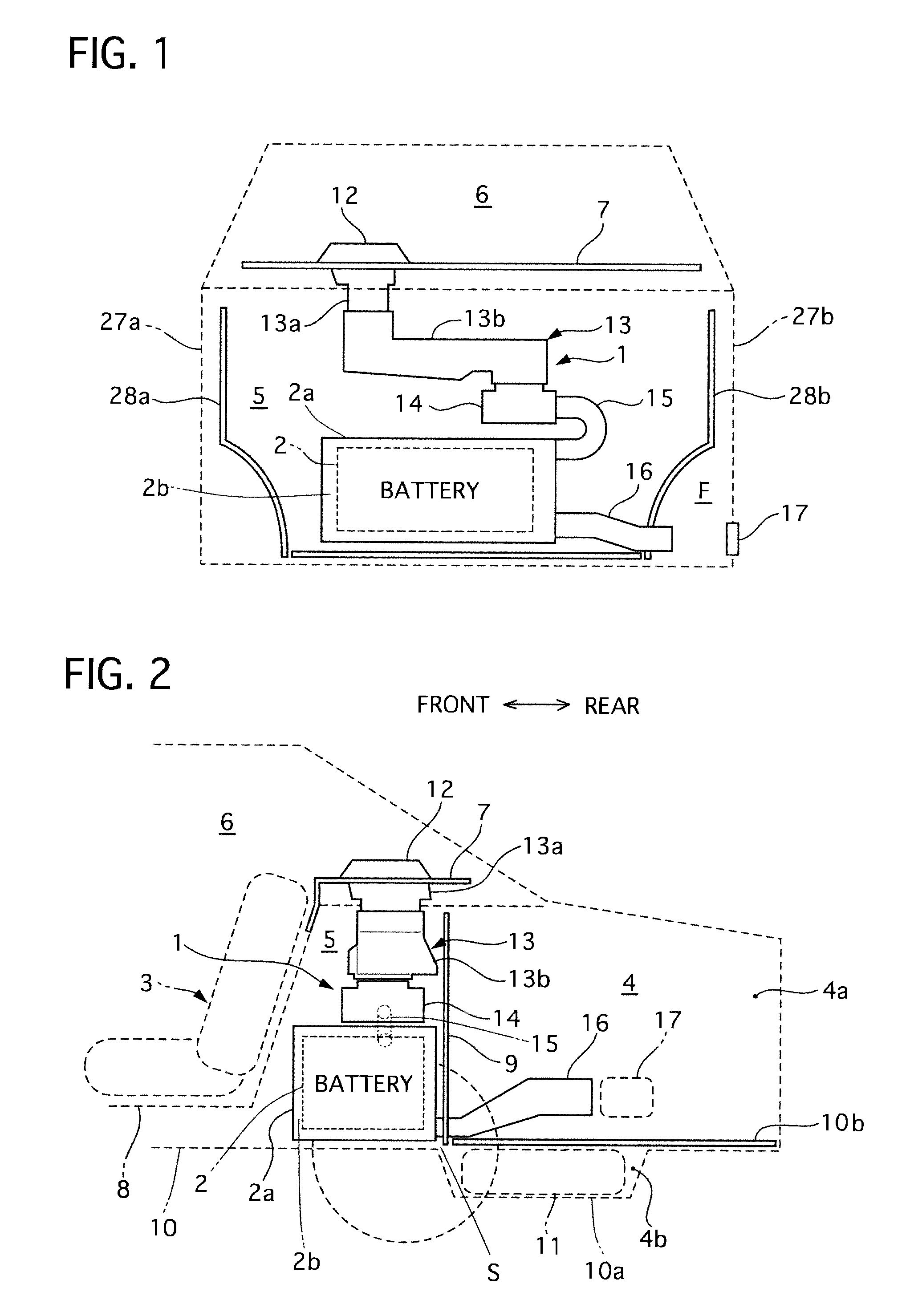
[0034]Referring to FIG. 1 and FIG. 2 of the drawings, there is shown the first embodiment of the structure for cooling the heat element in a state where it is mounted on a rear portion of the electric vehicle.

[0035]The structure 1 for cooling the battery 2 is installed in a battery storage space 5 which is formed between a passenger compartment 6 and a rear luggage compartment 4.

[0036]An interior panel 8 and an interior trim 7 define the battery storage space 5 from the passenger compartment 6. ...


PUM

PropertyMeasurementUnit
structureaaaaaaaaaa
volumeaaaaaaaaaa
electric poweraaaaaaaaaa

Abstract

A structure for cooling a heat element includes a heat element box containing a heat element and forms an air passageway therebetween, an intake duct connecting a passenger compartment and the air passageway, a discharge duct connecting the air passageway and a vehicle exterior, and a wall on a vehicle body. The intake duct has a water reserving portion for accumulating a liquid entering from the passenger compartment. The intake duct has an expansion portion and has a discharge hole of the liquid. The wall is provided to face the discharge hole so that the liquid discharged through the discharge hole moves downward along a surface of the wall.

Description

BACKGROUND OF THE INVENTION[0001]1. Field of the Invention[0002]The present invention relates to a structure for cooling a heat element such as a battery.[0003]2. Description of the Related Art[0004]A conventional structure for cooling a heat element of this kind is disclosed in Japanese Patent Application Laid-Open Publication N0. 07-132859.[0005]This prior structure for cooling the heat element is applied to an electric vehicle for example to cool its battery. This structure has an air duct for supplying a battery mounted under a floor panel with the open air so as to cool the battery. The air duct is provided with a water reserving portion so as to trap water and splash entering from a vehicle exterior to prevent them from entering the battery.[0006]However, in the above known conventional a structure for cooling a heat element, there are problems in that, although the water reserving portion of the air duct can accumulate the entering liquid such as water and splash and avoid it...

Claims


Application Information

Patent Timeline
Patent Type & Authority Patents(United States)
IPC IPC(8): B60K11/06H05K7/20H01M10/60H01M10/613H01M10/625H01M10/6563
CPCB60H1/00278H01M10/5073H01M10/5016H01M10/5004B60H2001/003B60L58/26H01M10/613H01M10/625H01M10/6566Y02E60/10Y02T10/70
Inventor YAMATANI, EIJI
Owner HIGHLY MARELLI JAPAN CORPORATION
Why Eureka
Try Eureka