
System and method for increasing bit-depth in a video display system using a pulsed lamp

pulsed lamp technology, applied in the field of video display systems, can solve the problems of limited bit depth of spatial light modulator-based display systems, temporal dither noise that is noticeable in the images produced by display systems, etc., and achieve the effect of increasing the bit depth of a video display system

Active Publication Date: 2013-04-30
TEXAS INSTR INC
View PDF6 Cites 0 Cited by
  • Summary
  • Abstract
  • Description
  • Claims
  • Application Information

AI Technical Summary

Benefits of technology

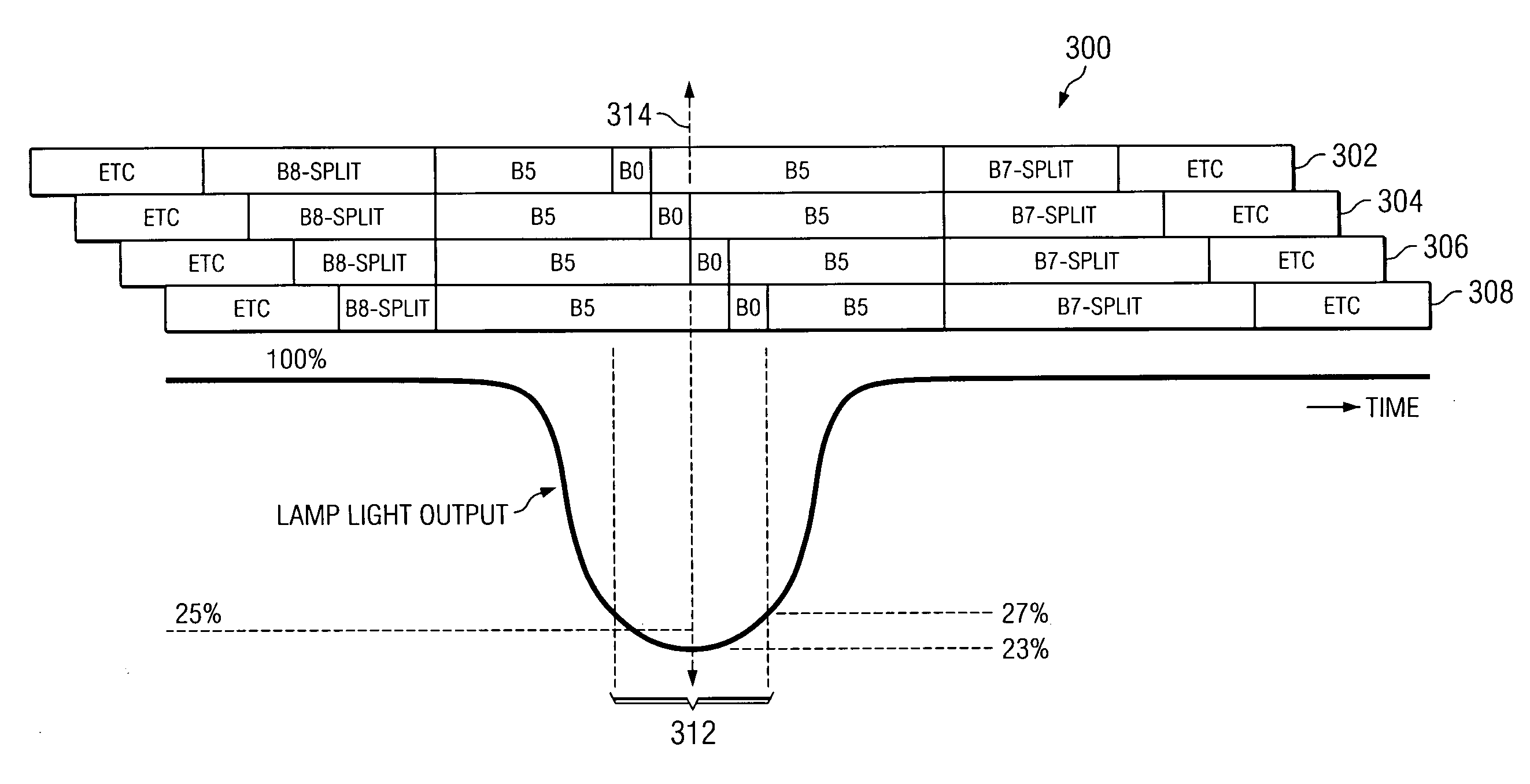
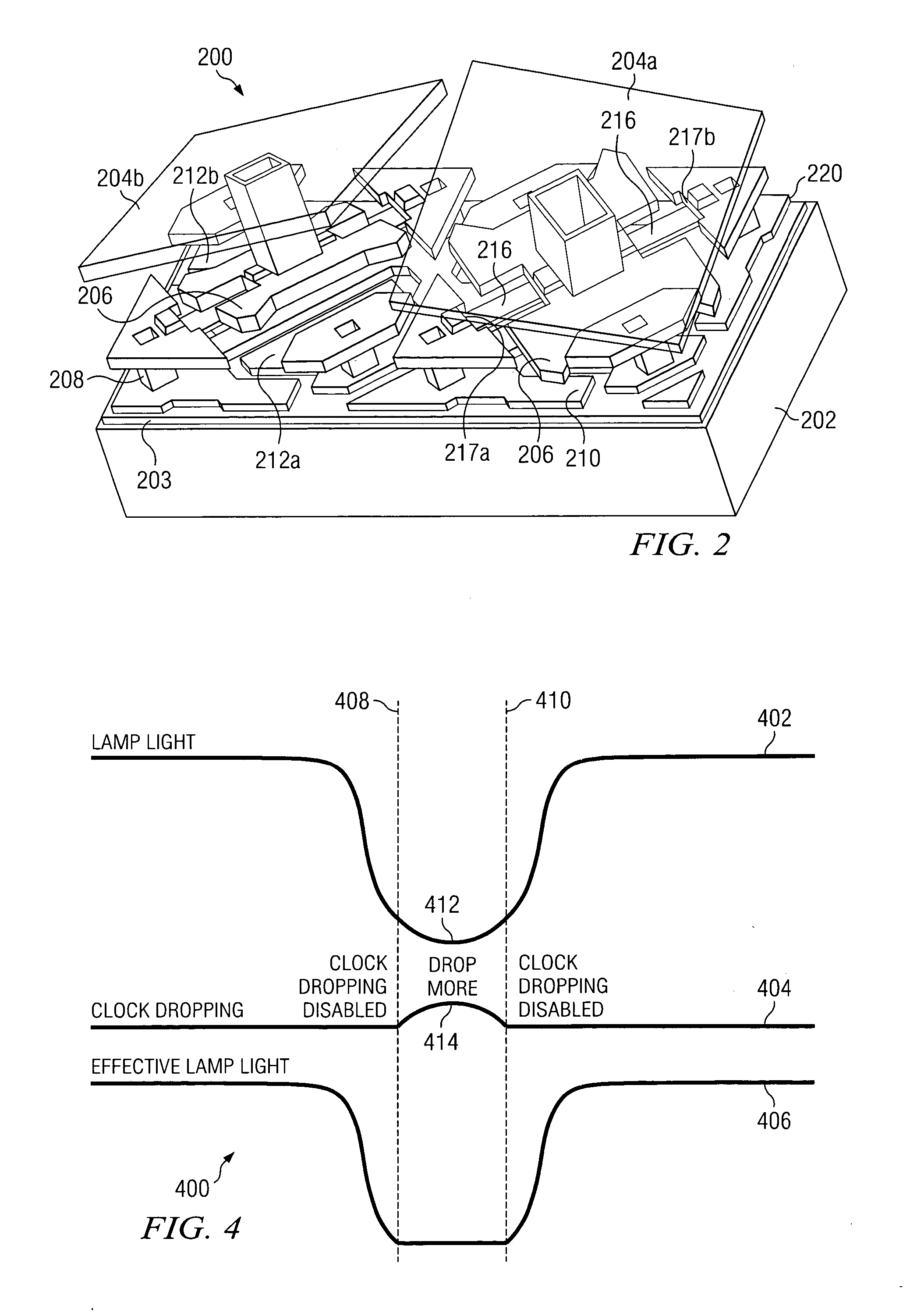
[0005]In accordance with the teachings of the present invention, a system and method for increasing the bit-depth of a video display system using a pulsed lamp are provided. In one embodiment, the method comprises illuminating a digital micro-mirror device with a light source having a variable power supply, receiving a signal indicating the light output provided to the digital micro-mirror device by the light source should be reduced to a target level during a predetermined time period, reducing a power supplied to the light source by the variable power supply in response to the signal such that the light output of the light source is reduced to about a target level during the predetermined time period, displaying a least significant bit on the digital micro-mirror device during the predetermined time period, and decreasing a speed of a master clock controlling the digital micro-mirror device in response to the light output of the light source deviating below the target level during the predetermined time period.
[0006]A technical advantage of some embodiments of the present invention includes the ability to increase the bit-depth of a spatial light modulator-based video display system despite the mechanical limitations of the spatial light modulator. In particular embodiments, this increased bit-depth may be achieved with reduced spatial contouring artifacts and / or temporal artifacts due to dither noise.

Problems solved by technology

Unfortunately, the bit-depth of spatial light modulator-based display systems is limited by on the minimum size of the LSB, which is in turn limited by the minimum transition time of the individual elements of modulator.
However, these techniques, while increasing the effective number of bits (and thus end-user perceivable bit-depth) available via spatial and temporal dithering, may cause temporal dither noise that is noticeable in the images produced by the display systems.

Method used


Image

  • System and method for increasing bit-depth in a video display system using a pulsed lamp
  • System and method for increasing bit-depth in a video display system using a pulsed lamp
  • System and method for increasing bit-depth in a video display system using a pulsed lamp

Examples


Embodiment Construction

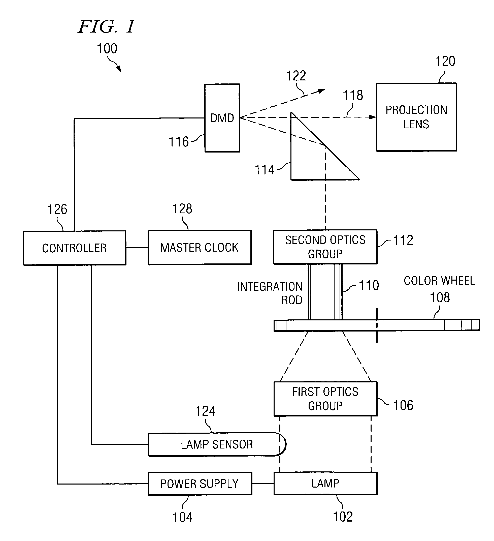
[0013]In accordance with the teachings of the present invention, a system and method for increasing the bit-depth of a video display system are provided. Generally, particular embodiments of the present invention increase the number of bits displayed by a spatial light modulator, such as a digital micro-mirror device (“DMD”), by reducing the light output from the light source illuminating the modulator and applying lower significance bits, herein referred to as “short bits,” during the reduced light output. In this manner, the bit-depth, or number of colors the display system may display, may be increased without relying on dithering or other techniques that may introduce unwanted artifacts to the image being displayed. Although a particular embodiment is described herein in the context of a DMD, the teachings of the present invention are also applicable to other spatial light modulators, and are not limited to digital micro-mirror devices.

[0014]FIG. 1 illustrates a block diagram of...


PUM


Abstract

In accordance with the teachings of the present invention, a system and method for increasing the bit-depth of a video display system using a pulse lamp are provided. In one embodiment, the method includes illuminating a digital micro-mirror device with a light source having a variable power supply, receiving a signal indicating the light output provided to the digital micro-mirror device by the light source should be reduced to a target level during a predetermined time period, reducing a power supplied to the light source by the variable power supply in response to the signal such that the light output of the light source is reduced to about a target level during the predetermined time period, displaying a least significant bit on the digital micro-mirror device during the predetermined time period, and decreasing a speed of a master clock controlling the digital micro-mirror device in response to the light output of the light source deviating below the target level during the predetermined time period.

Description

TECHNICAL FIELD[0001]This invention relates generally to video display systems employing spatial light modulators, and more particularly to a system and method for increasing bit-depth in a video display system using a pulsed lampBACKGROUND[0002]Spatial light modulators are devices that may be used in a variety of optical communication and / or video display systems. These device generate an image by controlling a plurality of individual elements that deflect light to form the various pixels of the image. One example of a spatial light modulator is a digital micro-mirror device (“DMD”).[0003]Typically, spatial light modulators, such as DMDs, operate by pulse width modulation (“PWM”). Generally, the incoming data signal or image is digitized into samples using a predetermined number of bits for each element. This predetermined number of bits is often referred to as the “bit-depth” of the modulator, particularly in systems employing binary bit weights. Generally, the greater the bit-dep...

Claims


Application Information

Patent Timeline
Patent Type & Authority Patents(United States)
IPC IPC(8): G09G3/34
CPCH04N5/7458H04N9/3155
Inventor MORGAN, DANIEL J.
Owner TEXAS INSTR INC
Learn More