Increased intensity resolution for pulse-width modulation-based displays with light emitting diode illumination

a technology of pulse-width modulation and intensity resolution, applied in the field of video display system, can solve the problems of reducing illumination for the entire time, limiting the speed at which the light modulator can be turned on and off, and unable to emit light with different intensity levels, etc., to achieve shorten the minimum amount of light produced, increase bit depth, and speed up the effect of ra

Active Publication Date: 2011-03-29
TEXAS INSTR INC
View PDF11 Cites 0 Cited by
  • Summary
  • Abstract
  • Description
  • Claims
  • Application Information

AI Technical Summary

Benefits of technology

In accordance with another preferred embodiment of the present invention, a system for displaying video images is provided. The system includes a spatial light modulator and a rapid switching light source that can optically illuminate the spatial light modulator. The spatial light modulator creates images made up of pixels by setting each light modulator in an array of light modulators into a state matching a corresponding pixel value, while the rapid switching light source is capable of switching at a faster rate than a rate of state switching by the spatial light modulator.
An advantage of a preferred embodiment of the present invention is that the use of LEDs for illumination can mean that LEDs can simply replace projector lamps in existing binary SLM designs. Therefore, implementation of the present invention can be achieved with very little modification to existing designs.
A further advantage of a preferred embodiment of the present invention is that when used in conjunction with a light modulator (for example, a mirror), the ability of the LEDs to rapidly turn on and off and produce light in a wide range of intensities can lead to a binary SLM with the capability to produce a wide range of light intensities. This can yield a binary SLM with an increased bit-depth.
Yet another advantage of a preferred embodiment of the present invention is that the ability to shorten the minimum amount of light producible by a binary SLM display system by using techniques other than shortening the light modulator switching time can result in a relaxation of design criteria and performance characteristics for the light modulators. The relaxation of the design criteria and performance characteristics can permit the use of lower cost and better tested manufacturing techniques and materials to create the light modulators, for example. Furthermore, the light modulators themselves may not have to be pushed as close to their performance limits to meet desired performance characteristics. Therefore, the light modulators may be cheaper and more reliable, as well as having higher manufacturing yields.

Problems solved by technology

A binary spatial light modulator (binary SLM), such as a binary micromirror device (DMD), is digital in nature and is not capable of emitting light with different intensity levels.
Being mechanical devices, there is a limit to how rapidly the light modulator can be turned on and off.
One disadvantage of the prior art is that the use of the NDF causes loss of light during the entire time of reduced illumination.
This loss of light results in a reduction of overall system brightness.
A second disadvantage of the prior art is that the use of the NDF or the dynamic aperture technology to modulate light amplitude can require modifications to existing binary SLM products and technologies, which can require significant redesign and redevelopment.
This can lead to the expenditure of a large amount of time and money.
A third disadvantage of the prior art is that both the NDF and the dynamic aperture technology techniques are mechanical techniques, which also have physical limits on a minimum amount of light that can be emitted.
Therefore, it may not be possible to reduce the minimum light intensity to a desired level if the physical limits are too high.
Additionally, mechanical techniques may not be able to provide a desired level of flexibility when it comes to exactly producing a needed level of light.

Method used


Image

  • Increased intensity resolution for pulse-width modulation-based displays with light emitting diode illumination
  • Increased intensity resolution for pulse-width modulation-based displays with light emitting diode illumination
  • Increased intensity resolution for pulse-width modulation-based displays with light emitting diode illumination

Examples


Embodiment Construction

The making and using of the presently preferred embodiments are discussed in detail below. It should be appreciated, however, that the present invention provides many applicable inventive concepts that can be embodied in a wide variety of specific contexts. The specific embodiments discussed are merely illustrative of specific ways to make and use the invention, and do not limit the scope of the invention.

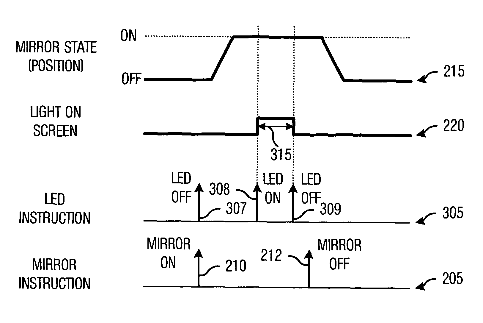
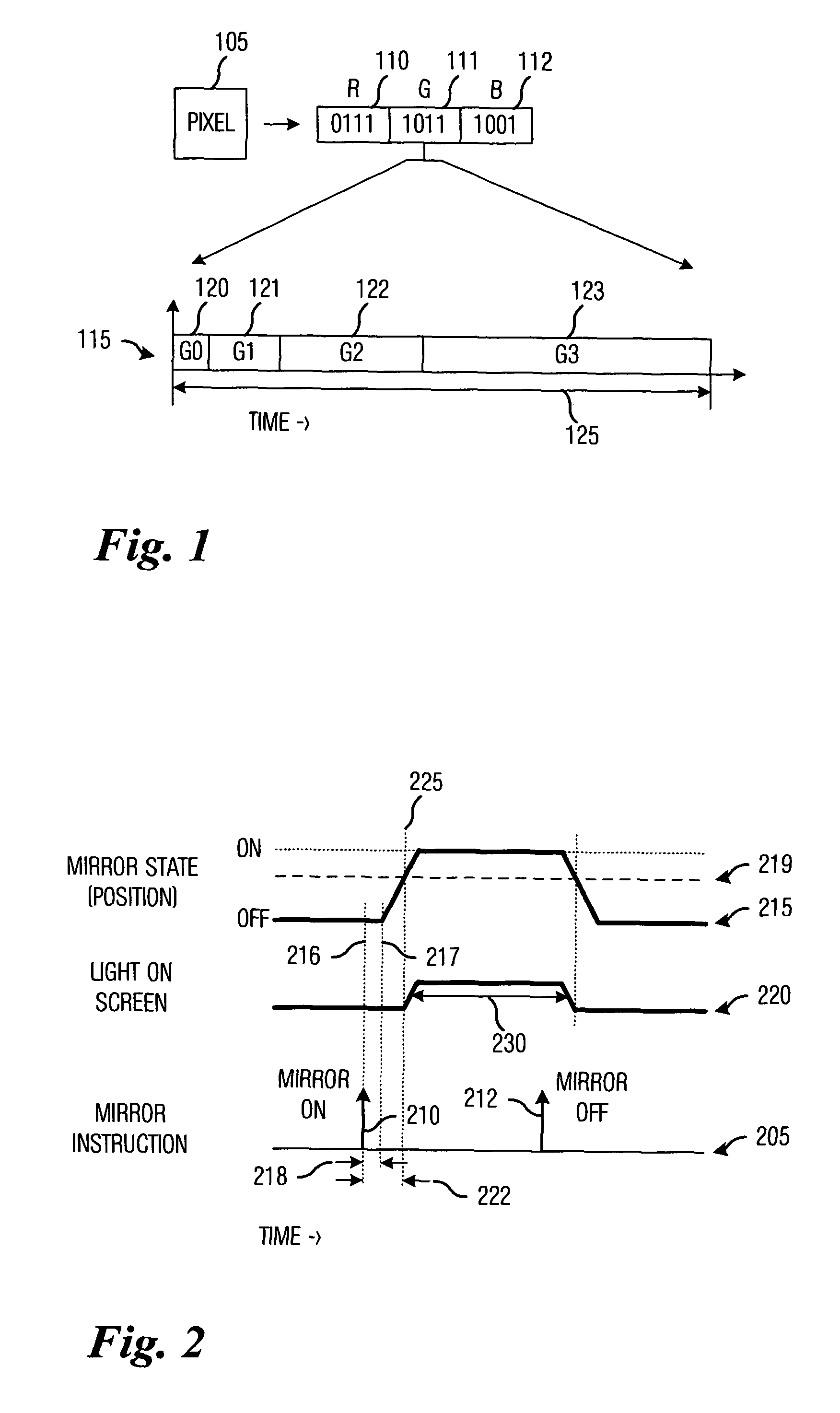
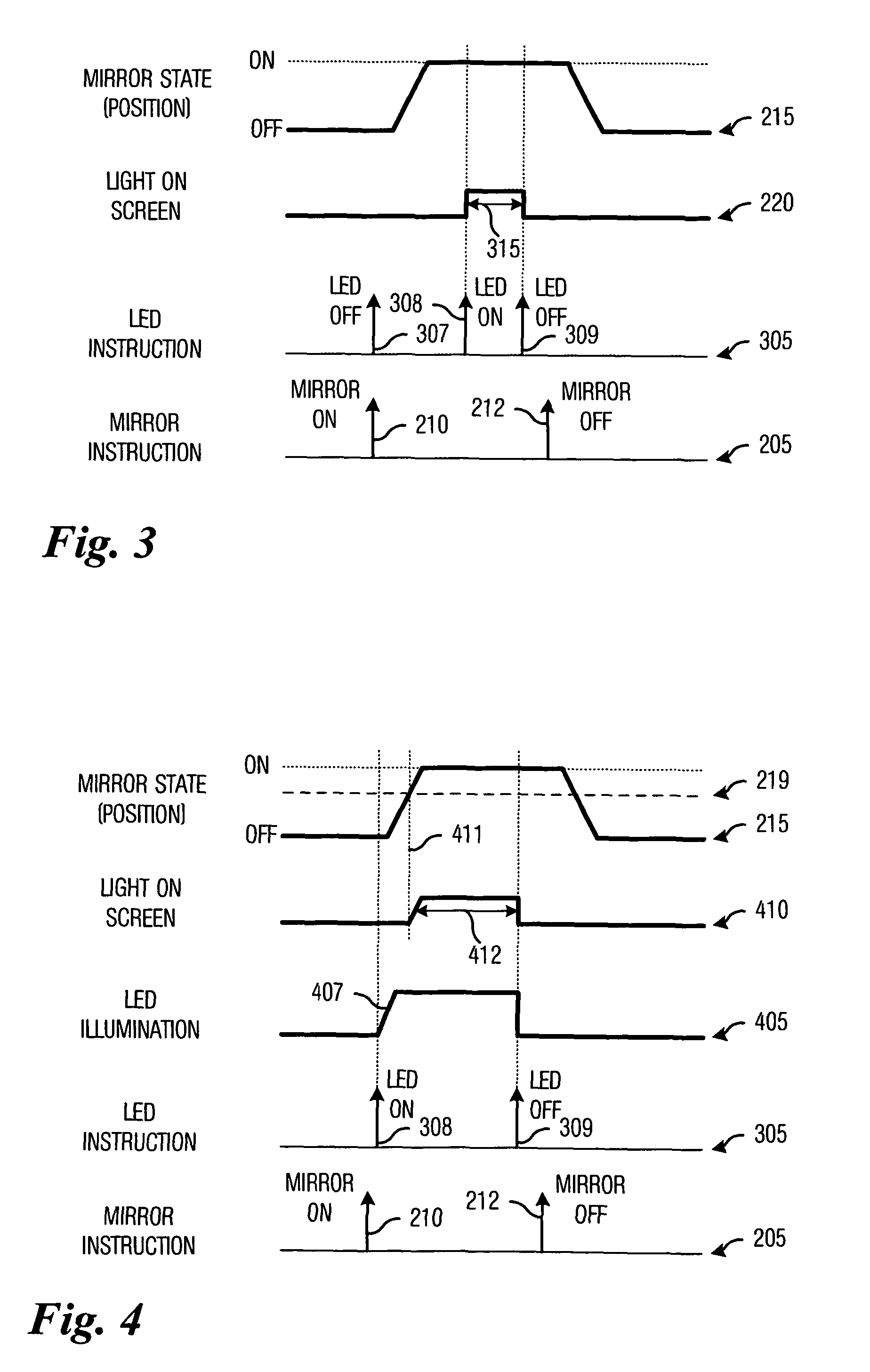
The present invention will be described with respect to preferred embodiments in a specific context, namely a binary SLM display system that makes use of mirrors as light modulators. The invention may also be applied, however, to other binary SLM display systems, wherein a light modulator is used to attenuate light intensity arising from a fixed light source. Examples of these binary SLM display systems can be display systems making use of liquid crystal display technology, liquid crystal on silicon technology, deformable mirror technology, actuated mirror technology, and so forth....


PUM


Abstract

A method for increasing intensity resolution (bit-depth) using LED illumination. A preferred embodiment comprises determining a display time for a bit to be displayed on a display system, with the display time being based upon a weighting of the bit. If the display time is less than a minimum display time of the display system, then a light modulator and light source modulation are to be used to display the bit. If the display time is equal to or greater than the minimum display time, then a light modulator is to be used to display the bit. The use of a light source that can switch at a faster rate than the light modulator can change states and / or a light source that can produce light at multiple intensities can permit the display of less light and thereby increase the bit-depth of the display system.

Description

TECHNICAL FIELDThe present invention relates generally to a system and method for video display systems, and more particularly to a system and method for increasing intensity resolution (bit-depth) using LED illumination.BACKGROUNDIn a typical video display system, images can be created by either emitting or modulating light. The light forms picture elements (pixels), which, when viewed together with other pixels, form an image. The pixels in an image will typically have a variety of colors and / or intensities, with image quality being dependent upon a number of different intensity levels the pixels are capable of displaying. A binary spatial light modulator (binary SLM), such as a binary micromirror device (DMD), is digital in nature and is not capable of emitting light with different intensity levels. However, there may be other SLMs that can be digital in nature but are not binary. Instead, the binary SLMs will typically rely on a pulse width modulation (PWM) scheme to create ligh...

Claims


Application Information

Patent Timeline
Patent Type & Authority Patents(United States)
IPC IPC(8): G09G3/34
CPCG09G3/3406G09G3/346G09G3/2014G09G2320/0252G09G2320/0646
Inventor HEWLETT, GREGORY JAMESDOHERTY, DONALD B.
Owner TEXAS INSTR INC
Why Eureka
Try Eureka