Illumination system with integral modulation technique

a projection display and integrated modulation technology, applied in the field of projection display systems, can solve the problems of difficult to achieve perceptible increases in quality, affecting the quality of visual images, and occupying a relatively large space for crt, so as to improve the contrast of visual images and increase bit depth

Active Publication Date: 2007-06-07
TEXAS INSTR INC
View PDF9 Cites 3 Cited by
  • Summary
  • Abstract
  • Description
  • Claims
  • Application Information

AI Technical Summary

Benefits of technology

[0008] The present invention is directed at an efficient illumination system that modulates the light in a projection in order to, for example, increase bit depth and improve contrast in the visual images produced by the system. The system and method of the presenting invention also alleviate problems typically associated with excess heat buildup that are encountered when using prior modulation schemes.

Problems solved by technology

The selection, operation, and configuration of these devices also contributes to unseen characteristics of the system, such as cost and efficient use of system resources.
This technology is fairly well-developed, but has reached the point where perceptible increases in quality are difficult to achieve.
A CRT also takes up a relatively-large amount of space because the components used for generating the electron stream must be placed at a certain distance from the display screen.
In addition, the light may be intermittently blocked, altering the quality of light available for reflection by the DMD micromirrors.
Current methods for blocking the light path, however, generally require the absorption of light by elements that form part of the optical path itself.
Frequently, this produces problems related to the undesirable buildup of excess heat energy.

Method used


Image

  • Illumination system with integral modulation technique
  • Illumination system with integral modulation technique
  • Illumination system with integral modulation technique

Examples


Embodiment Construction

[0025] The making and using of the presently preferred embodiments are discussed in detail below. It should be appreciated, however, that the present invention provides many applicable inventive concepts that can be embodied in a wide variety of specific contexts. The specific embodiments discussed are merely illustrative of specific ways to make and use the invention, and are not intended to limit its scope.

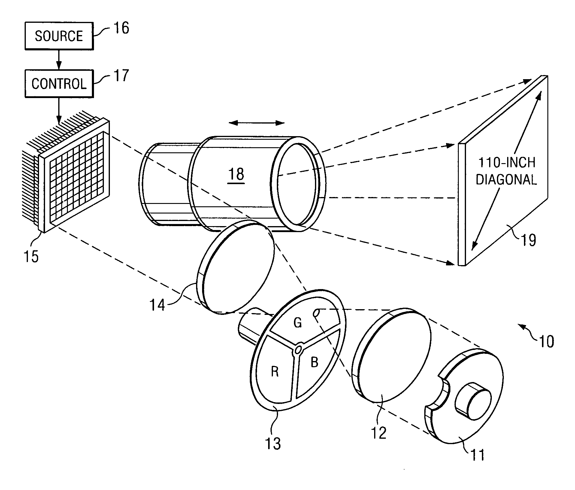
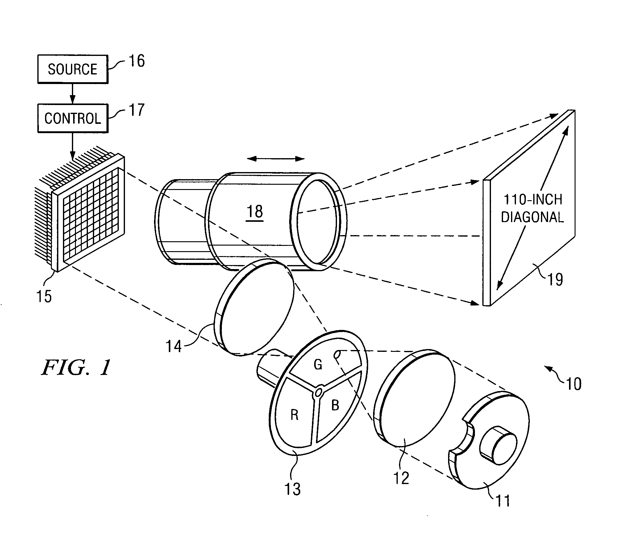
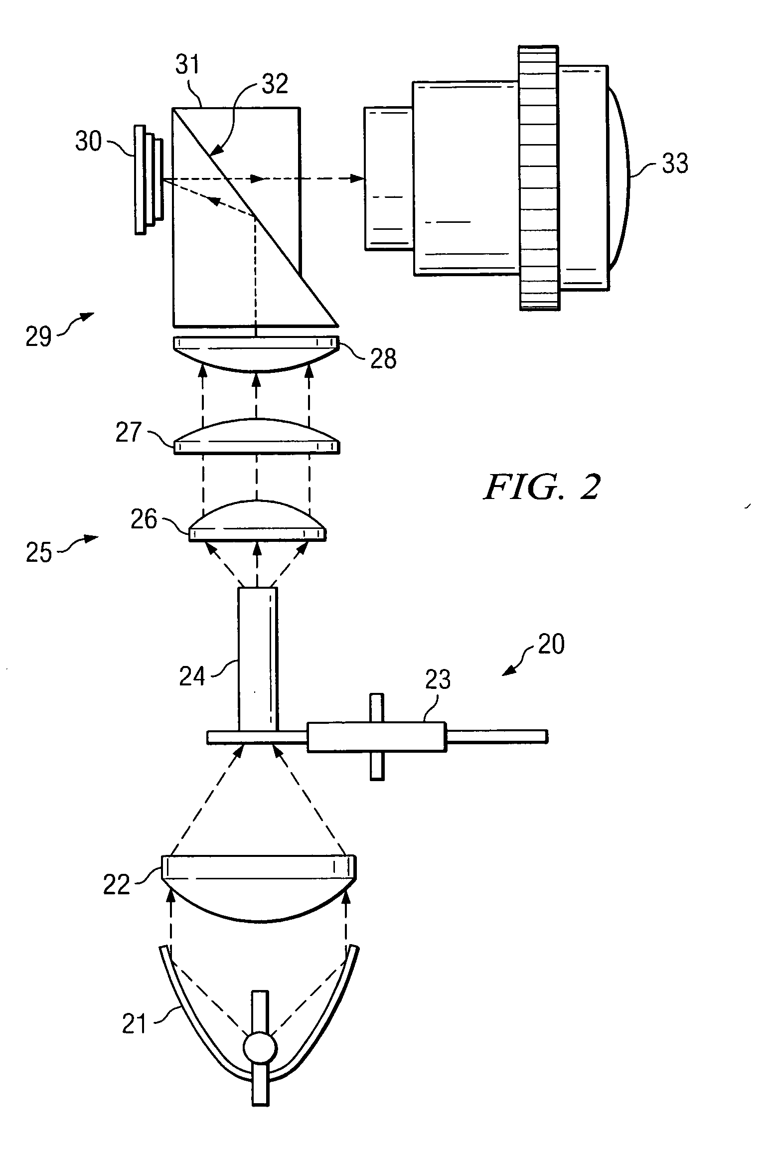
[0026] The present invention will be described with respect to preferred embodiments in a specific context, namely a projection display system that produces visual images on a display screen using spatial light modulation (SLM). The invention may also be applied to advantage, however, in other optical systems that modulate light to produce visual images for display.

[0027] Naturally, in any projection display system one goal is to produce a visual image of high quality on the visual image display screen. The techniques used to accomplish this goal, however, generally are limite...


PUM


Abstract

A system and method for the modulation of light propagating along an optical path, for example the optical path in a projection display system. As light in the optical path travels from a light source to a display screen, it is shaped and modulated by the various components of the optical path so that the intended visual image appears on the display screen. In accordance with the present invention, a mirror disposed proximate the optical path is operable to be selectively inserted and removed from the optical path to alternately direct the light from one portion of the optical path to another, or to a light dump where it can be absorbed such that the associated heat energy may be properly dissipated. In a preferred embodiment, the mirror is a fold mirror mounted at a stop of the system to fold the light beam approximately 90 degrees when the mirror is inserted in the optical path.

Description

TECHNICAL FIELD [0001] The present invention relates generally to the field of projection display systems, and relates more particularly to a display system employing an illumination relay coincident with a fold mirror located at a stop in the system that is operable to selectively retract and insert into the optical path for directing downstream light transmission in a manner that improves system efficiency. BACKGROUND [0002] Projection displays are used for a wide variety of applications, such as producing the pictures viewed on television screens. A typical projection display system includes a number of components, including the screen, a light source, and an optical path between them. To create the pictures, one or more light sources are provided to emit light when it is needed. The light they produce is then manipulated by a series of optical devices in order to create the visual image. The visual image created along the optical path is then displayed on the visual-image displa...

Claims


Application Information

Patent Timeline
Patent Type & Authority Applications(United States)
IPC IPC(8): G02B26/00
CPCG02B26/0833H04N9/3155
Inventor DEWALD, DUANE SCOTTDAVIS, MICHAEL T.SAWYERS, BRYCE DANIEL
Owner TEXAS INSTR INC
Why Eureka
Try Eureka