
Node of a distributed communication system, node and monitoring device coupled to such communication system

a communication system and node technology, applied in the field of nodes of distributed communication systems, can solve problems such as errors or defective behavior, and achieve the effects of reducing complexity, increasing error detection, and high availability

Active Publication Date: 2013-04-30
NXP BV
View PDF11 Cites 6 Cited by
  • Summary
  • Abstract
  • Description
  • Claims
  • Application Information

AI Technical Summary

Benefits of technology

The present invention aims to provide a node, a distributed communication system, and a monitoring device that can increase error detection and reduce complexity for providing a high availability solution for non-100% fail safe systems. This will make the system more robust and reliable in detecting and responding to failures, thereby increasing its overall efficiency and reliability.

Problems solved by technology

If the monitoring device recognizes a non-defined behavior of the communication controller which has the possibility to disrupt the communication of other nodes, the monitoring device will signal the erroneous or defective behavior of the communication controller to the host.

Method used


Image

  • Node of a distributed communication system, node and monitoring device coupled to such communication system
  • Node of a distributed communication system, node and monitoring device coupled to such communication system
  • Node of a distributed communication system, node and monitoring device coupled to such communication system

Examples


Embodiment Construction

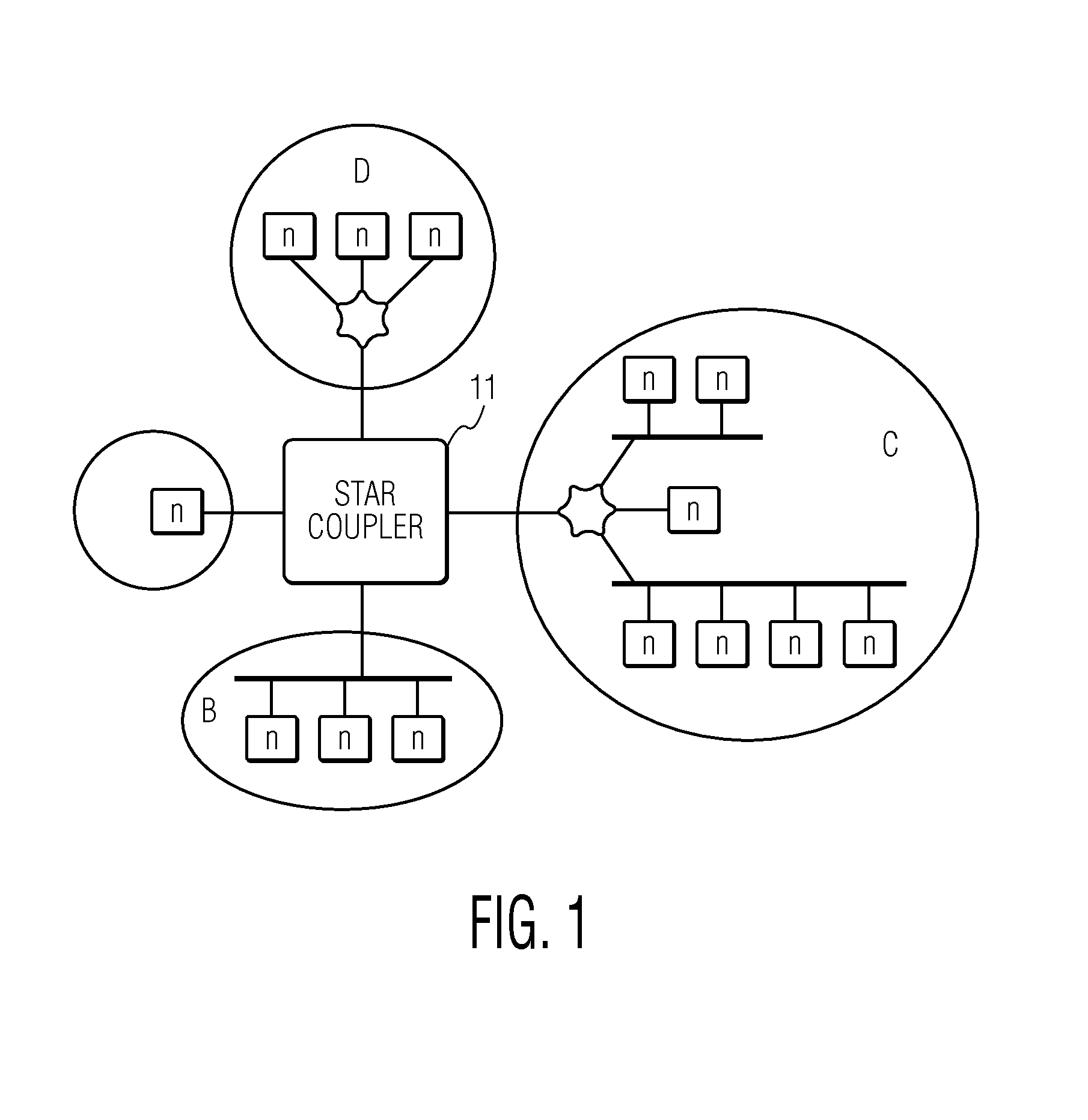
[0043]FIG. 1 illustrates a communication system as used in the present invention. The communication system illustrated in FIG. 1 is divided into a number of sub-nets (A-D), each of them be supported by a passive bus or by a star-coupler.

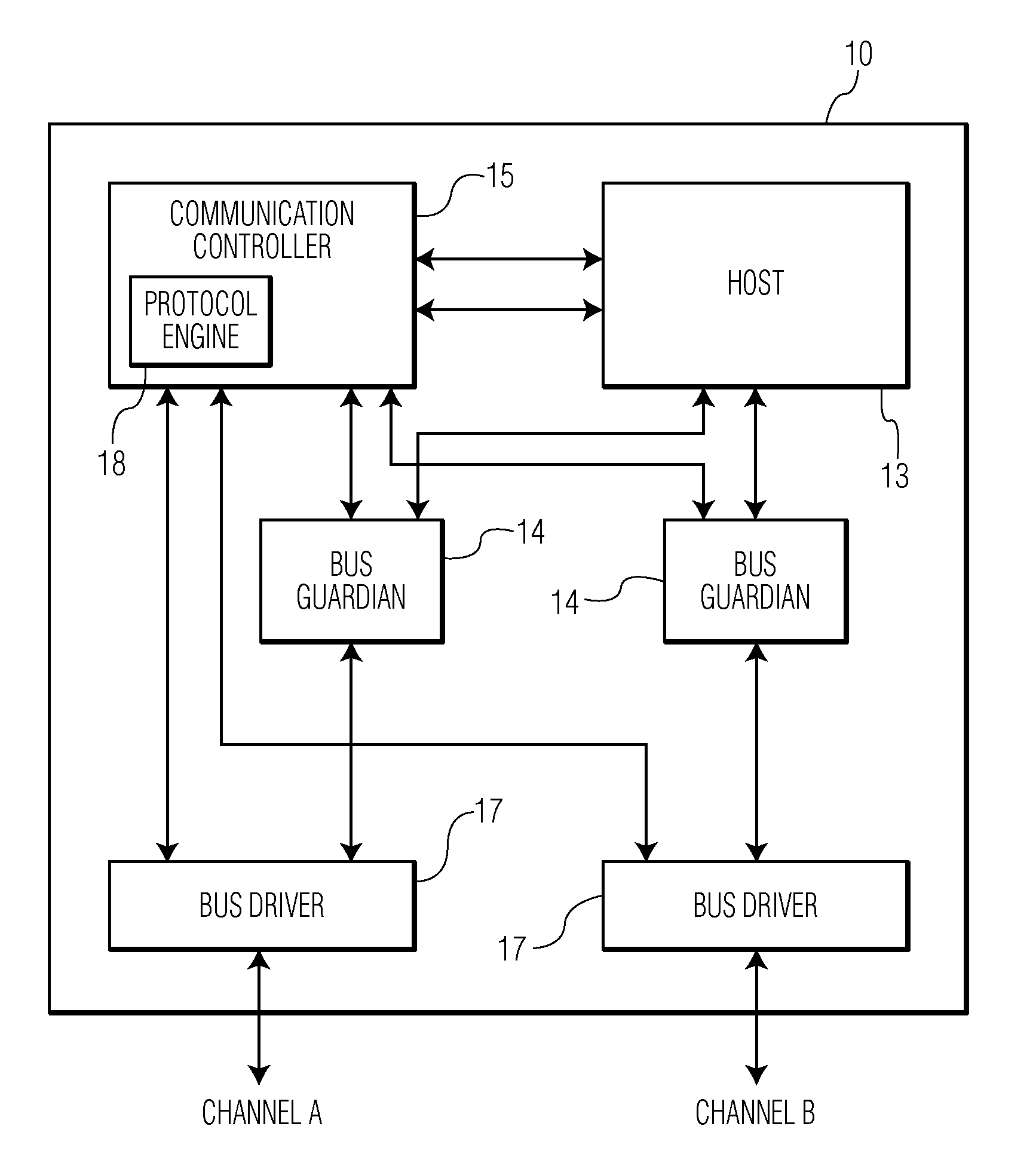
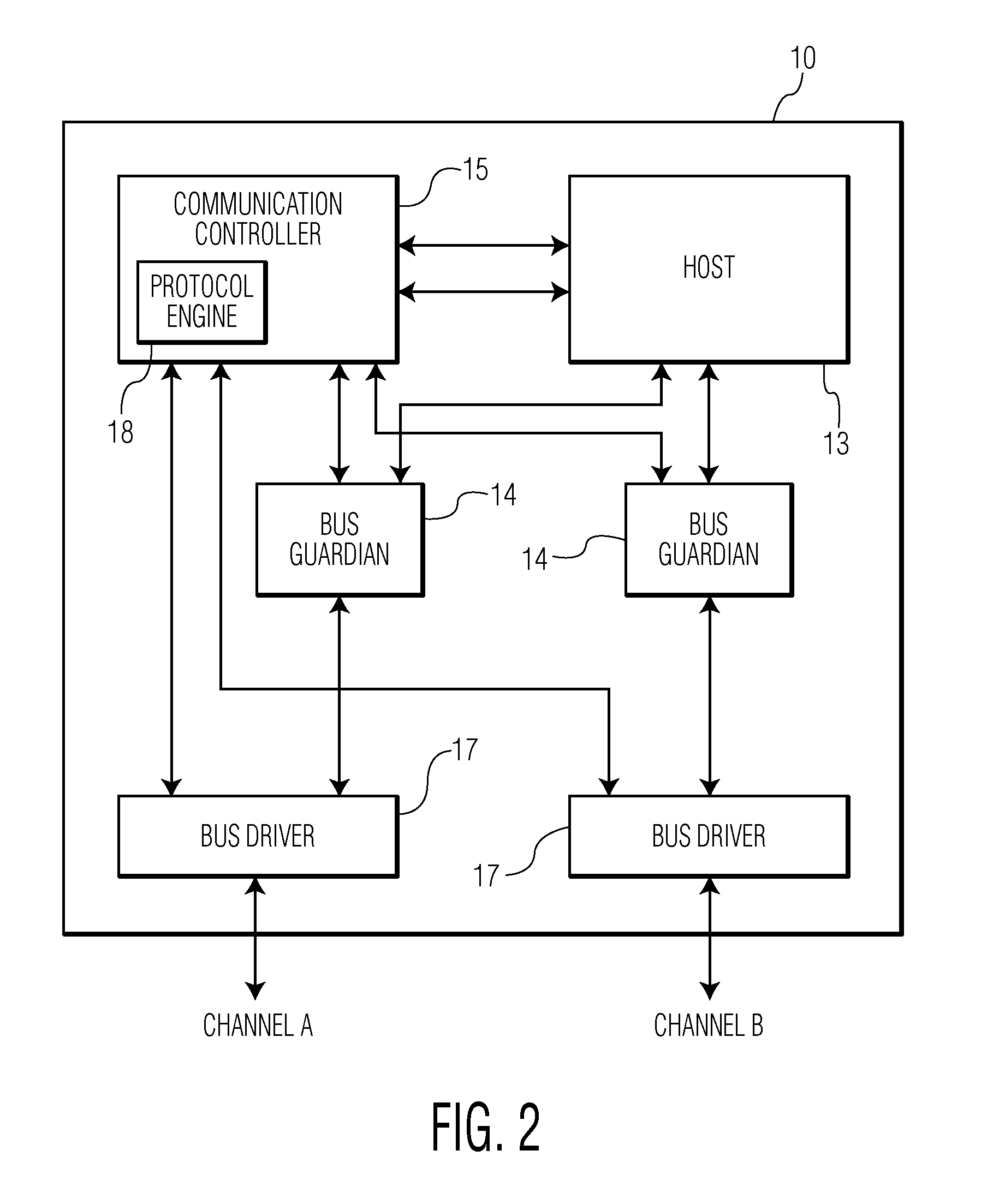
[0044]With reference to FIG. 2, a node 10 used in such sub-net is described in more detail. A typical fault-tolerant time-triggered network consists usually of two communication channels A, B, to which nodes 10 are connected. Each of those nodes 10 comprises a bus driver 17, a communication controller 15 and eventually a bus guardian device 14 for each bus driver and a host 13. The bus driver 17 transmits the bits and bytes that the communication controller 15 provides onto its connected channels and in turn provides the communication controller 15 with the information it receives from the channels A, B. The communication controller 15 is connected to both channels and delivers relevant data to the host 13 and receives data from the host 13. The comm...


PUM


Abstract

The present invention relates to a node in distributed communication system operating under a time triggered protocol, further it relates to distributed communication system and to a monitoring device coupled to such node of a communication system. To provide a node in a distributed communication system, a distributed communication system and a monitoring device increasing the error detection and reducing complexity for providing a high availability for systems which require a non 100% fail safe solution a node is proposed comprising: a communication controller (15) coupled to a receiving and a transmission path, a host (13) for performing an application, and a monitoring device (16) coupled at least to one of a transmission path of the communication controller (15), an interface (91) between communication controller (15) and the host (13), and to internal lines of the communication controller (15), wherein the monitoring device (16) is provided for evaluating information provided by the communication controller (15) to monitor at least one state of the communication controller (15), wherein in case of detecting a non-defined state the host (13) is informed for performing predetermined actions in respect to the state of the communication controller (15). Thereby, an easy cost reduced solution is provided adapted to detect a predetermined number of faults in a distributed communication system.

Description

FIELD OF THE INVENTION[0001]The present invention relates to a node of a distributed communication system, further it relates to a distributed communication system and to a monitoring device coupled to such node of a communication system.BACKGROUND OF THE INVENTION[0002]There are some protocols used in distributed communication systems. In the automotive area especially time-triggered protocols are used. One of such protocols is the FlexRay protocol. The FlexRay communication protocol is the answer of the automotive industry to the increasing demands for reliable, high-speed data communication in the automotive area, or similar applications. The FlexRay communication protocol is based on a TDMA scheme to coordinate access of participating devices to the communication system. But it avoids to employ a master synchronizing node within the automotive communication system to achieve a decentralized more fault robust bus architecture. This requires a mutual synchronization of all partici...

Claims


Application Information

Patent Timeline
Patent Type & Authority Patents(United States)
IPC IPC(8): G01R31/08H04L69/40
CPCH04L12/40013H04L12/40026H04L12/44H04L2012/40241H04L2012/40273
Inventor FUHRMANN, PETERBAUMEISTER, MARKUS
Owner NXP BV
Learn More