Method and system for fuel vapor control

a technology of fuel vapor control and fuel tank, which is applied in the direction of condensed fuel collection/return, charge feed system, non-fuel substance addition to fuel, etc. it can solve the problems of unpredictability of the amount of fuel vapors bled from the fuel tank to the canister, disturbance of air-to-fuel ratio, etc., to reduce engine operation times, reduce fuel emissions benefits, and enable fuel economy

Active Publication Date: 2013-05-07
FORD GLOBAL TECH LLC
View PDF14 Cites 31 Cited by
  • Summary
  • Abstract
  • Description
  • Claims
  • Application Information

AI Technical Summary

Benefits of technology

[0002]Reduced engine operation times in hybrid vehicles, such as plug-in hybrid vehicles, enable fuel economy and reduced fuel emissions benefits. However, the shorter engine operation times can lead to insufficient purging of fuel vapors from the vehicle's emission control system. To address this issue, hybrid vehicles may include a fuel tank isolation valve (FTIV) between a fuel tank and a hydrocarbon canister of the emission system to limit the amount of fuel vapors absorbed in the canister. Engine control systems may coordinate fuel tank pressure relief with refueling and canister purging operations to enable emissions control.
[0006]By adjusting the purging from the fuel tank based on a buffer capacity, loading of fuel vapors from the fuel tank to the buffer may be better controlled. In particular, by delivering fuel vapors as multiple purge pulses, rather than as a single purge, with each pulse adjusted based on the buffer capacity, buffer loading may be better controlled and air-to-fuel ratio disturbances may be reduced. By cyclically unloading a canister buffer before loading the buffer with fuel vapors from the fuel tank, purging of fuel vapors from the fuel tank may be better coordinated with purging of fuel vapors from the canister.
[0009]In this way, overloading of the buffer is reduced, and overflow of fuel vapors from the buffer into the canister is reduced. By further adjusting the pulses based on the fuel tank pressure, fuel tank pressure may be maintained within limits without causing air-to-fuel ratio disturbances. As such, this leads to improved exhaust emissions.

Problems solved by technology

However, the shorter engine operation times can lead to insufficient purging of fuel vapors from the vehicle's emission control system.
However, the inventors herein have identified a potential issue with such an approach.
As one example, air-to-fuel ratio disturbances may arise since canister loading may be more variable (and less predictable) than canister unloading.
Specifically, since the FTIV is kept open until the desired fuel tank pressure is reached, the amount of fuel vapors bled from the fuel tank to the canister may vary unpredictably.
For example, there may be sudden fuel vapor spikes during the unloading of fuel vapors from the canister.
In one example, the fuel vapor spikes from the fuel tank may overload the canister leading to higher air-to-fuel ratio disturbances and degraded exhaust emissions.

Method used


Image

  • Method and system for fuel vapor control
  • Method and system for fuel vapor control
  • Method and system for fuel vapor control

Examples


Embodiment Construction

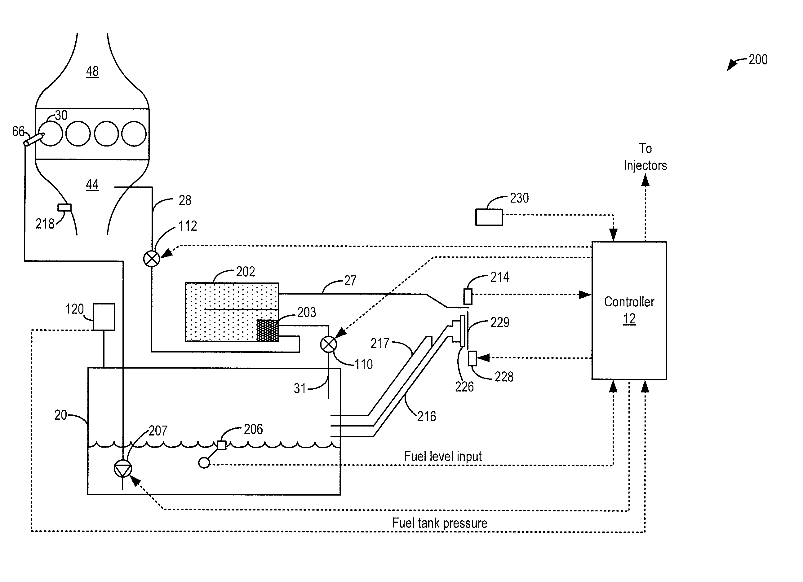
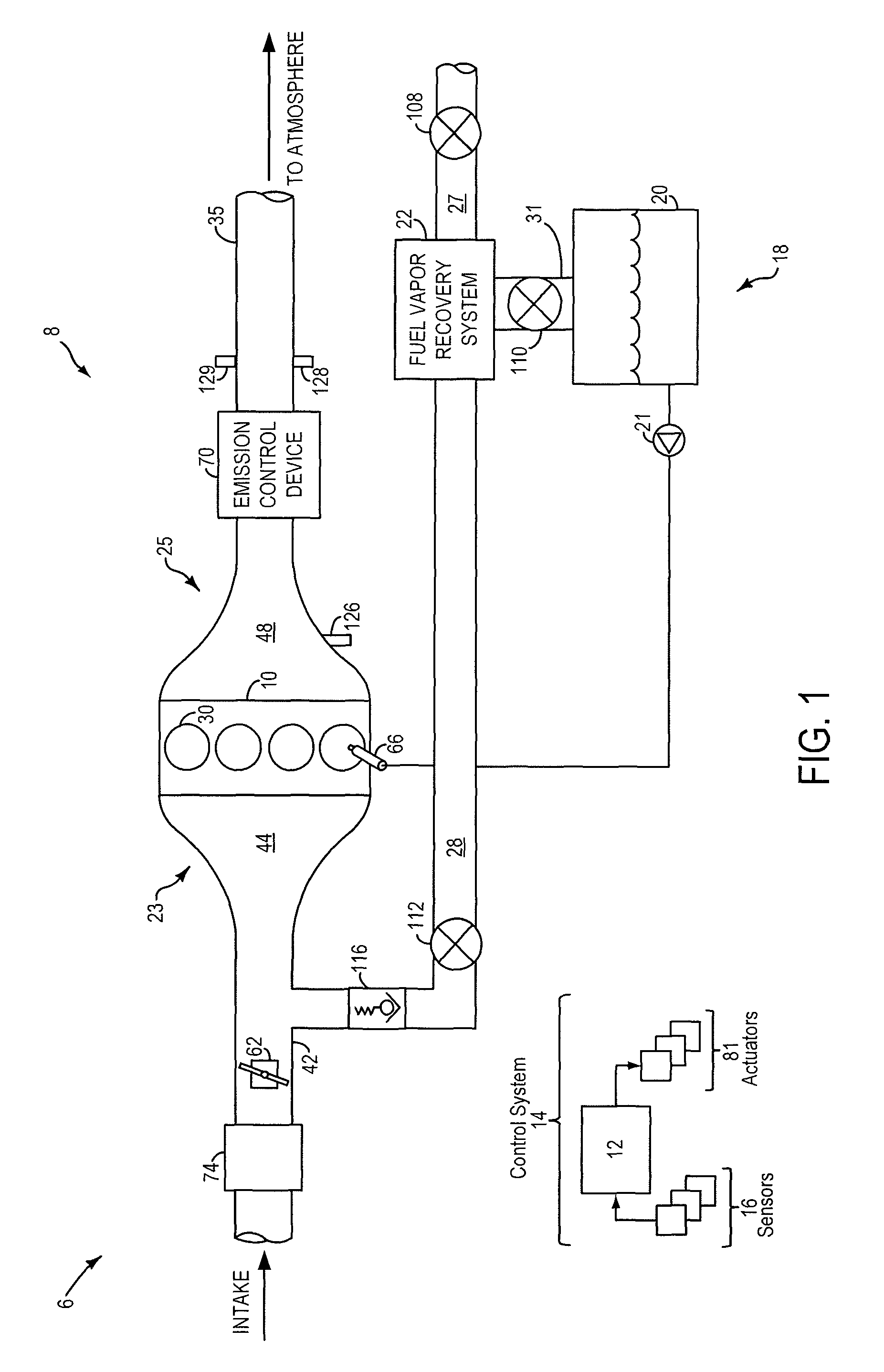
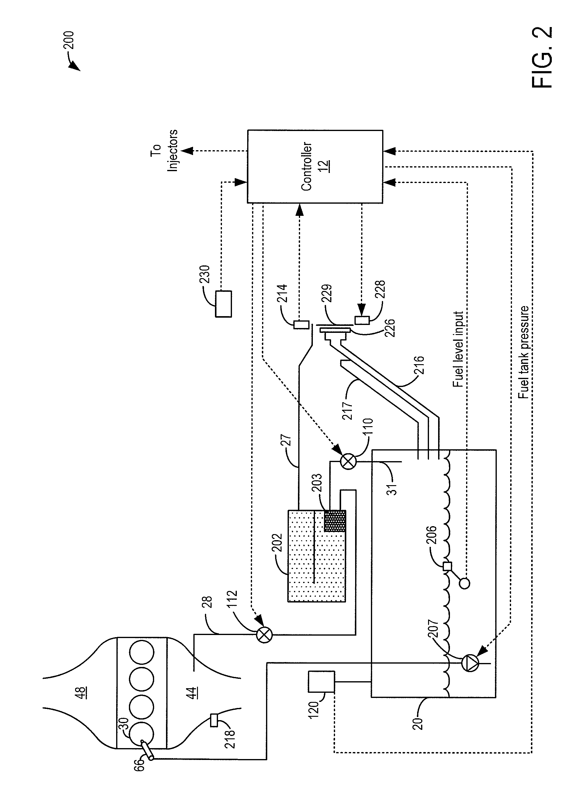
[0017]The following description relates to systems and methods for operating a fuel vapor recovery system, such as the system of FIG. 2, coupled to an engine system, such as the engine system of FIG. 1. During purging conditions, a purge valve may be opened to purge fuel vapors stored in a canister to the engine intake. Following the purging from the canister, a fuel tank isolation valve (FTIV) of the fuel vapor recovery system may be intermittently opened to purge fuel vapors from the fuel tank to a buffer region of the canister over a number of purge pulses. A duration of each purge pulse, as well as an interval between consecutive pulses may be adjusted based on the buffer capacity, purge flow rate, and the fuel tank pressure (e.g., at the onset of the pulsing). An engine controller may be configured to perform control routines, such as those depicted in FIGS. 3-5, to adjust the duration of, and interval between, the pulses and coordinate purging from the canister to the engine i...


PUM


Abstract

Methods and systems are provided for operating a fuel vapor recovery system having a fuel tank isolation valve coupled between a fuel tank and a canister. Fuel vapors are purged from the fuel tank to a canister buffer over a plurality of purge pulses. The pulses are adjusted based on the buffer capacity, a purge flow rate, and a fuel tank pressure to improve control of canister loading and reduce air-to-fuel ratio disturbances.

Description

FIELD[0001]The present application relates to fuel vapor purging in vehicles, such as hybrid vehicles.BACKGROUND AND SUMMARY[0002]Reduced engine operation times in hybrid vehicles, such as plug-in hybrid vehicles, enable fuel economy and reduced fuel emissions benefits. However, the shorter engine operation times can lead to insufficient purging of fuel vapors from the vehicle's emission control system. To address this issue, hybrid vehicles may include a fuel tank isolation valve (FTIV) between a fuel tank and a hydrocarbon canister of the emission system to limit the amount of fuel vapors absorbed in the canister. Engine control systems may coordinate fuel tank pressure relief with refueling and canister purging operations to enable emissions control.[0003]One example approach of emissions control is shown by Kidokoro et al. in U.S. Pat. No. 6,796,295. Therein, during engine operation, the FTIV is opened if a fuel tank pressure exceeds a limit and if the canister purge rate is hig...

Claims


Application Information

Patent Timeline
Patent Type & Authority Patents(United States)
IPC IPC(8): F02M33/02
CPCF02M25/08F02M25/089
Inventor KERNS, JAMES MICHAELKRAGH, CHRISYANG, DENNISDEBASTOS, TIMOTHYPEARCE, RUSSELL RANDALLBOHR, SCOTTHEIM, MICHAEL G.
Owner FORD GLOBAL TECH LLC
Why Eureka
Try Eureka