Display support structure and method

a support structure and display technology, applied in the direction of steering linkages, doors/windows, branching pipes, etc., can solve the problems of easy wear of clamps, inability to provide solid engagement between structural members, and inability to provide proper clamping, etc., to achieve convenient use, improve retention, and less wear

Active Publication Date: 2013-05-07
ORBUS P3 +1
View PDF10 Cites 22 Cited by
  • Summary
  • Abstract
  • Description
  • Claims
  • Application Information

AI Technical Summary

Benefits of technology

[0006]The present disclosure provides a connector for structural members or beams of a display, such as portable or permanent displays used in trade shows and the like, that is simple, easy to use, and provides improved retention and less wear over previously known designs. The effectiveness and ease of use of the disclosed connectors involves engagement of rotationally eccentric features. In a preferred embodiment, a user may simply depress the head of the fastener, which protrudes from the connector, slip the end of the structural member over the connector, and release the head of the fastener. The head of the fastener is configured to snap in place within a preformed hole located adjacent an end of the beam. An audible “click” informs the user of appropriate positioning, and even in the unlocked state, the fastener is able to retain the end of the beam in engagement with the connector. To lock the connector, a user may simply turn the fastener to engage the cam feature and rigidly constrain the end of the beam onto the connector.

Problems solved by technology

Although such known clamps are effective in joining structural members lengthwise, the clamps can easily become worn.
They also cannot provide a solid engagement between the structural members.
Such known clamps are also not well suited for providing proper axial or planar alignment between adjacent structural members.
Finally, they tend to be somewhat difficult to assembly and disassemble.

Method used


Image

  • Display support structure and method
  • Display support structure and method
  • Display support structure and method

Examples


Embodiment Construction

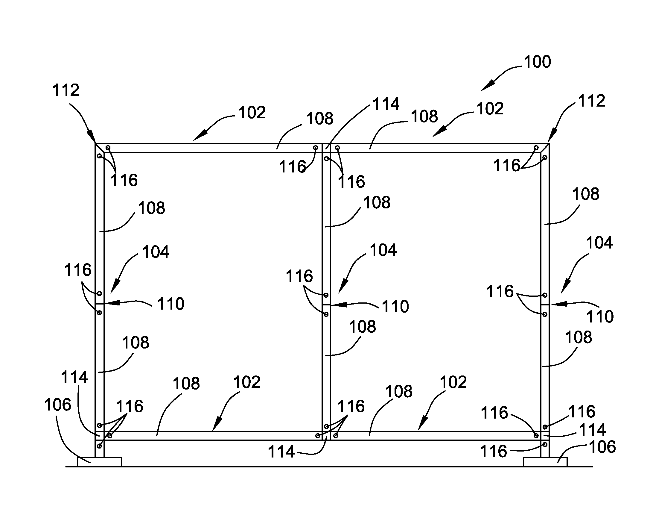
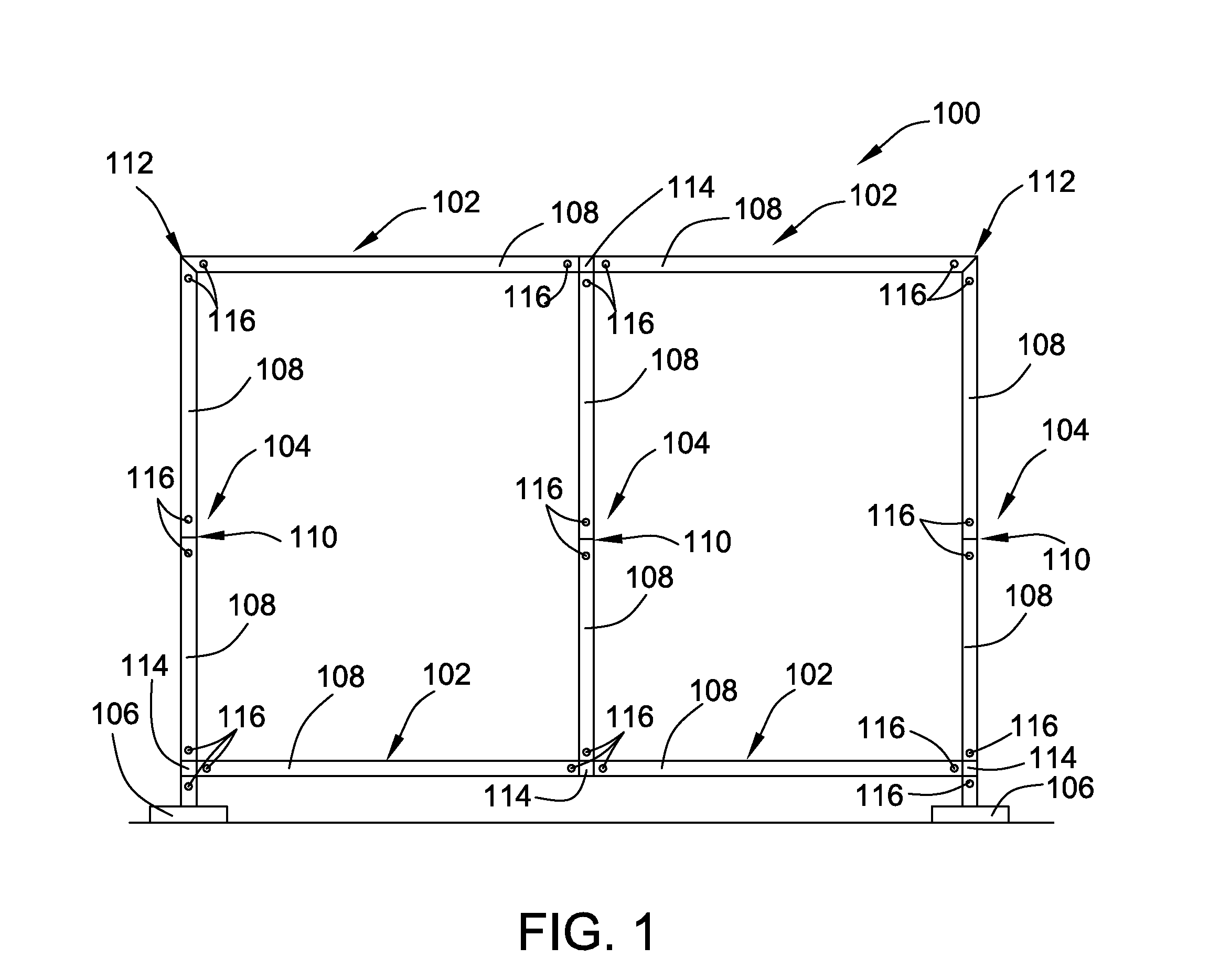
[0015]An exemplary arrangement of a display structure 100 is shown in FIG. 1. The display structure 100 is shown having a rectangular shape with horizontal members 102 and vertical members 104 that are interconnected to one another. The entire structure is held upright by two bases 106, and is configured to support display panels, shelves, video screens, lighting fixtures, and the like as is known. Although the display structure 100 is shown having a generally planar shape made up of linear structural members 102 and 104, any other shape can be provided in the known fashion for such displays.

[0016]In the illustrated embodiment, the display structure 100 is made up of linear beams 108 having a rectangular cross section and channels (not shown) running along the entire length of each beam 108. The beams 108 are connected at their respective ends to provide rigid structural joints that form the structure of the display 100. A few examples of joint types are shown in FIG. 1, but it shou...


PUM

PropertyMeasurementUnit
angleaaaaaaaaaa
angleaaaaaaaaaa
angleaaaaaaaaaa

Abstract

A connector for rigidly engaging elongate structural members in a display structure includes a beam connection portion defined on a body and having a cavity. A semi-cylindrical guide surface of the cavity is adjacent to an opening. The opening has an elliptical shape in which the difference between a major and a minor axis is an offset distance. An eccentric fastener is rotatably disposed in the cavity and includes a head portion that protrudes from the opening and engages a hole of the elongate structural member, and a cam portion that is eccentrically disposed relative to the head portion and configured to engage the semi-cylindrical surface when the eccentric fastener is rotated relative to the connector.

Description

BACKGROUND OF THE INVENTION[0001]The present invention relates to support structures for portable or permanent displays and the like, such as those used in trade shows. More particularly, the disclosure relates to an apparatus and method used to connect adjacent structural members of a display in a longitudinal direction.[0002]A typical display structural member is often in the form of a pulltruded aluminum beam having a generally rectangular cross section. The beam internally forms a generally rectangular hollow channel that is surrounded on two opposite sides by open channels. The open channels may extend along the entire length of the structural member and serve as anchoring features for adjustably connectable clamps and other locking devices, such as those used to mount display panels, shelves, lighting, tables, and other exhibit booth elements to the support structure.[0003]In the past, structural members for displays were connectable lengthwise to one another by use of removab...

Claims


Application Information

Patent Timeline
Patent Type & Authority Patents(United States)
IPC IPC(8): F16B21/00F16B21/02
CPCE04B1/5831F16B7/042F16B7/046G09F15/0068E04B2/7422Y10T403/5741Y10T403/55Y10T403/4671Y10T403/4651Y10T403/725Y10T24/4578Y10T403/18Y10T29/49947Y10T403/28Y10T29/49826Y10T403/5793F16B2200/40F16B2200/205F16B2200/65
Inventor ALKAS, DEANCARROW, MICHAEL
Owner ORBUS P3
Why Eureka
Try Eureka