
Base cup for a supportable pressurizable container

a technology of base cups and containers, which is applied in the direction of external fittings, large containers, packaging, etc., can solve the problems of not being able to sit upright on horizontal surfaces, the container cannot be attached to the bottom of the container, and the cost of material,

Active Publication Date: 2013-05-14
PROCTER & GAMBLE CO
View PDF43 Cites 56 Cited by
  • Summary
  • Abstract
  • Description
  • Claims
  • Application Information

AI Technical Summary

Benefits of technology

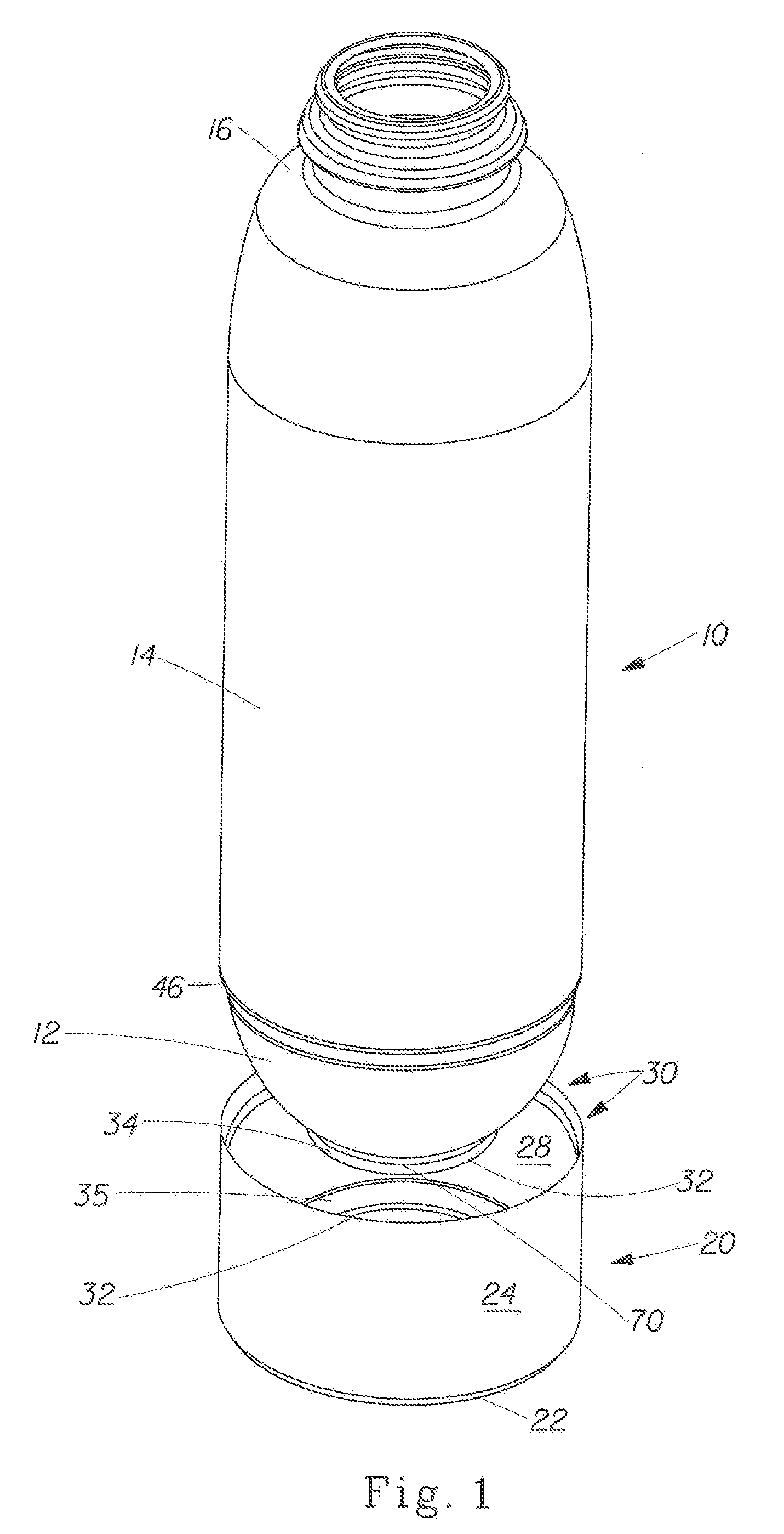
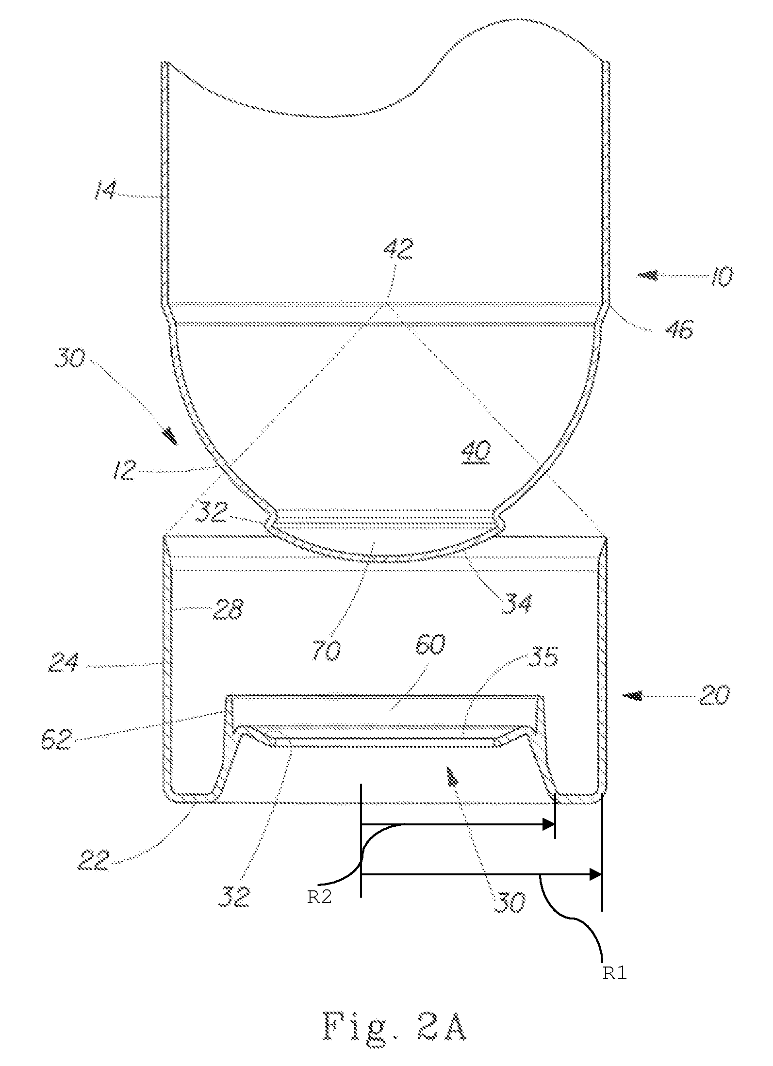
[0022]In one embodiment the invention may comprise a container and a base cup attached thereto. The container may have an irregular bottom and side walls visible when the container is disposed on a horizontal surface. The base cup fits over at least a portion of the bottom of the container and allows the container to sit upright on a horizontal surface. The container and base cup may have alignment tabs, which fit together and provide a reactive force of one component against the other to help maintain these components in the proper position when engaged.

Problems solved by technology

However, relatively thick walls present the problem of material cost and are viewed as environmentally unfriendly.
However, this approach provides the disadvantage that the curved base does not allow the container to sit upright on horizontal surfaces such as a shelf or table.
Attachment of the base cup to the bottom of the container has presented yet its own problems.
However, such engagement systems present their own problems.
This results in a noticeable line or ridge, which is unsightly.
This problem may be exacerbated when the container is pressurized.
However, when the container is pressurized, expansion may occur.
Such expansion may cause further mismatch at the interface between the mating edges of the container and base cup.
This approach provides the disadvantage that an additional material cost in the form of the adhesive occurs.
Yet other problems occur when the container uses a dip tube to dispense contents.
The dip tub may not be positioned at the lowest point of the container, allowing contents to be wasted.
However, this approach may not be feasible with a container having a hemispherical bottom designed to withstand internal pressure.

Method used


Image

  • Base cup for a supportable pressurizable container
  • Base cup for a supportable pressurizable container
  • Base cup for a supportable pressurizable container

Examples


Embodiment Construction

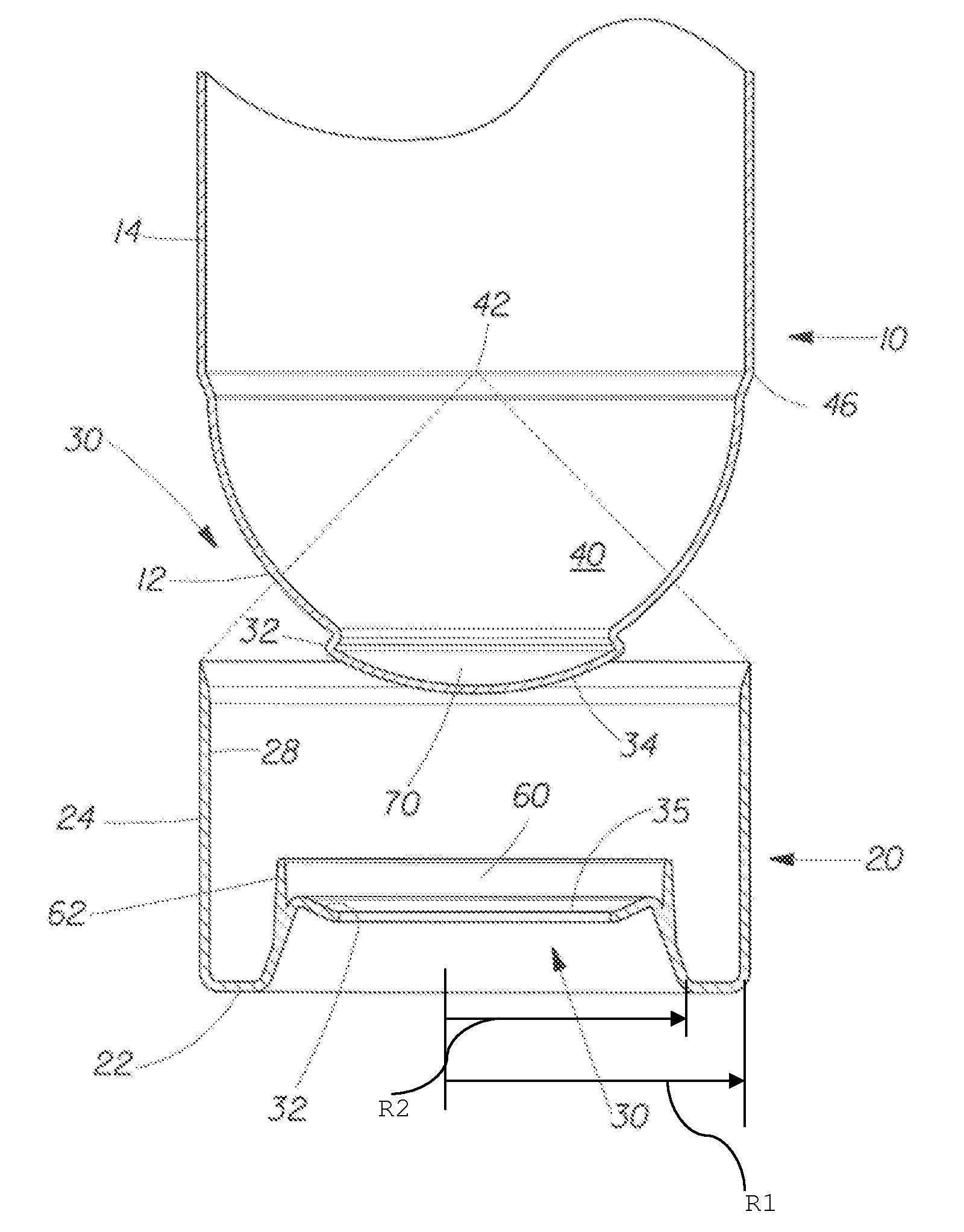
[0024]Referring to FIG. 1, the invention comprises a container 10, and more particularly the bottom portion thereof. The container 10 has a has a bottom 12, for indirectly resting upon a surface, a top 16 for dispensing the contents of the container 10 therefrom, and side walls 14 and joining in the bottom 12 and top 16. The container 10 may have a longitudinal axis through the bottom 12 and top 16. The longitudinal axis may be generally vertical when the container 10 is disposed on a horizontal surface. The container 10 may be joined to a complementary base cup 20 for resting upon a surface.

[0025]Referring to FIGS. 2A and 2B and examining the components in more detail, the bottom 12 of the container 10 may be irregular, and not allow the container 10 to stand upright on a horizontal surface. The bottom 12 of the container 10 may be eccentric, sloped, tapered, curved, and more particularly, hemispherical as shown. As used herein, an irregular bottom 12 is any bottom 12 not having a ...


PUM


Abstract

A container having a curved bottom and base cup which allows the container to stand upright. The container and base cup are fitted together by a mechanical engagement having portions on the container and base cup. The mechanical engagement of the container is disposed within the bottom cone of the container. The mechanical engagement of the base cup is cantilevered from the bottom of the base cup. Such disposition reduces stress at the interface between the side wall of the container and edge of the base, providing for a smoother transition and better appearance. Also, this disposition provides resistance to separation of the container and base cup during drop impact. The bottom of the container may be curved and have a well therein for receiving the contents of the container and a dip tube.

Description

[0001]The present invention relates to containers having irregular bottoms and base cups for such containers.BACKGROUND OF THE INVENTION[0002]Pressurizable containers are well known in the art. Such containers are often used to hold and dispense consumer products, such as shaving cream, air fresheners, cleaners, furniture polish, etc. The container may be pressurized to a pressure greater than atmospheric pressure using propellants, inflatable bags, powered pumps, manual pumps such as a squeeze trigger, etc.[0003]The contents of the container, when pressurized, may be dispensed from a nozzle or other opening juxtaposed with the top of the container. For example, the top of the container may have a neck with a threaded cap as occurs with common soft drinks, so that the contents may simply be poured from the container when the cap is removed. Alternatively, the top of the container may be provided with a nozzle so that the contents are dispensed from the container as a foam, gel, mist...

Claims


Application Information

Patent Timeline
Patent Type & Authority Patents(United States)
IPC IPC(8): B65D1/02
CPCB65D23/001
Inventor SMITH, SCOTT EDWARDMARTIN, MATTHEW JOHNGIRARDOT, RICHARD MICHAELHUANG, CHOW-CHI
Owner PROCTER & GAMBLE CO
Learn More