
Broadband convex ground planes for multipath rejection

a convex ground plane and multipath technology, applied in the field of antennas, can solve the problems of limiting the use of flat ground planes, affecting the operation of the entire navigation system, and a major source of positioning errors of multipath reception, so as to reduce the frequency of multipath reception

Active Publication Date: 2013-05-14
TOPCON GPS
View PDF7 Cites 8 Cited by
  • Summary
  • Abstract
  • Description
  • Claims
  • Application Information

AI Technical Summary

Benefits of technology

The convex ground plane design provides a wider directivity pattern and better multipath rejection across a broader frequency range, improving satellite tracking capabilities and accommodating various components within compact navigation systems.

Problems solved by technology

Multipath reception is a major source of positioning errors in global navigation satellite systems (GNSSs).
Multipath reception adversely affects the operation of the entire navigation system.
The relatively large size limits the usage of flat ground planes, since many applications call for compact receivers.
A choke-ring ground plane contributes to undesirable narrowing of the antenna directivity pattern.
Narrowing the antenna directivity pattern results in poorer tracking capability for satellites with low elevations.
Also, the performance of a choke-ring structure is frequency-dependent.
Because new GNSS signal bands (such as GPS L5, GLONASS L3, and GALILEO E6 and E5) are being introduced, the overall frequency spectrum of GNSS signals is increasing significantly; consequently, traditional choke ring capabilities are becoming limited.
This structure is a dual-frequency unit and does not provide good multipath mitigation within the entire GNSS frequency range.

Method used


Image

  • Broadband convex ground planes for multipath rejection
  • Broadband convex ground planes for multipath rejection
  • Broadband convex ground planes for multipath rejection

Examples


Embodiment Construction

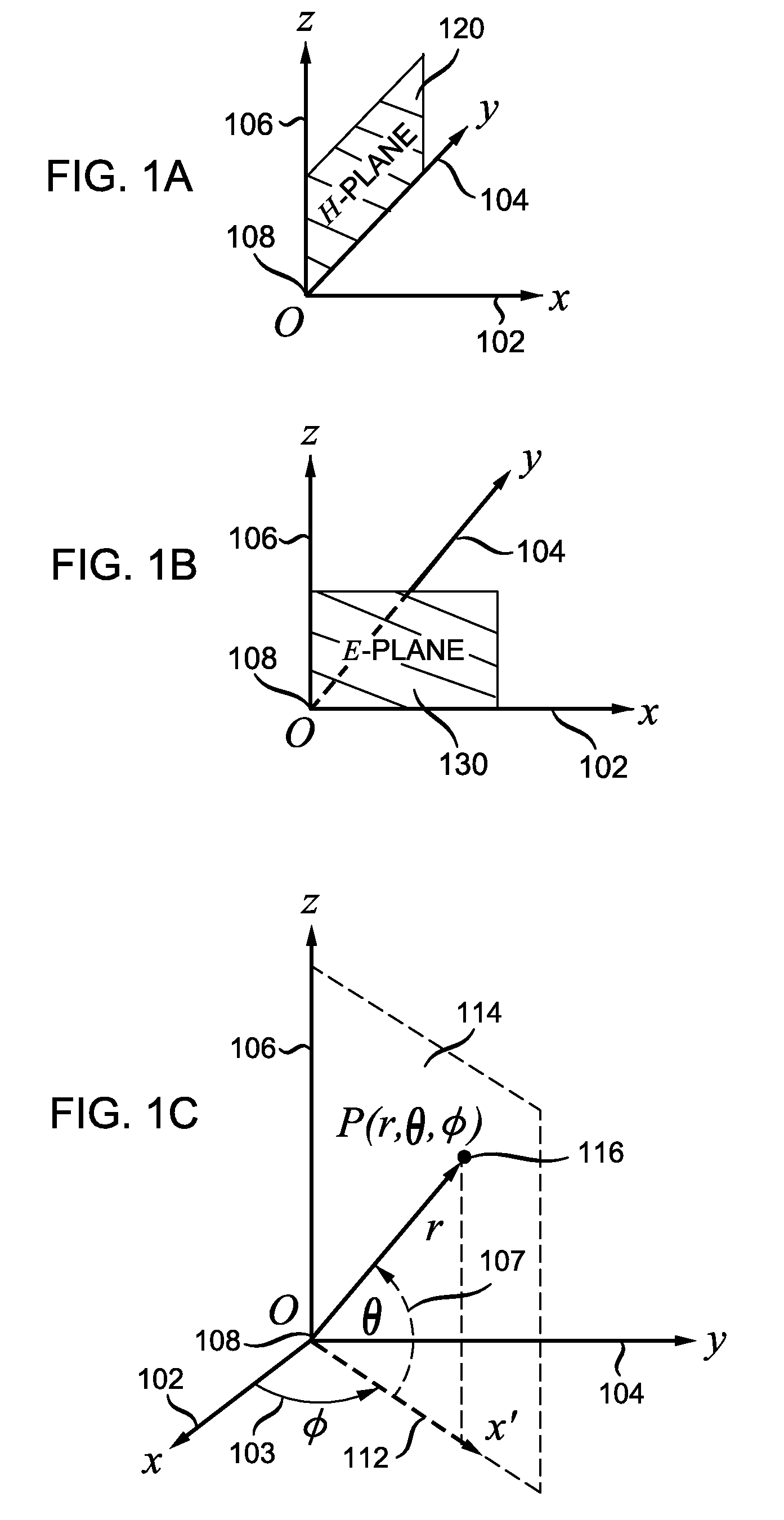
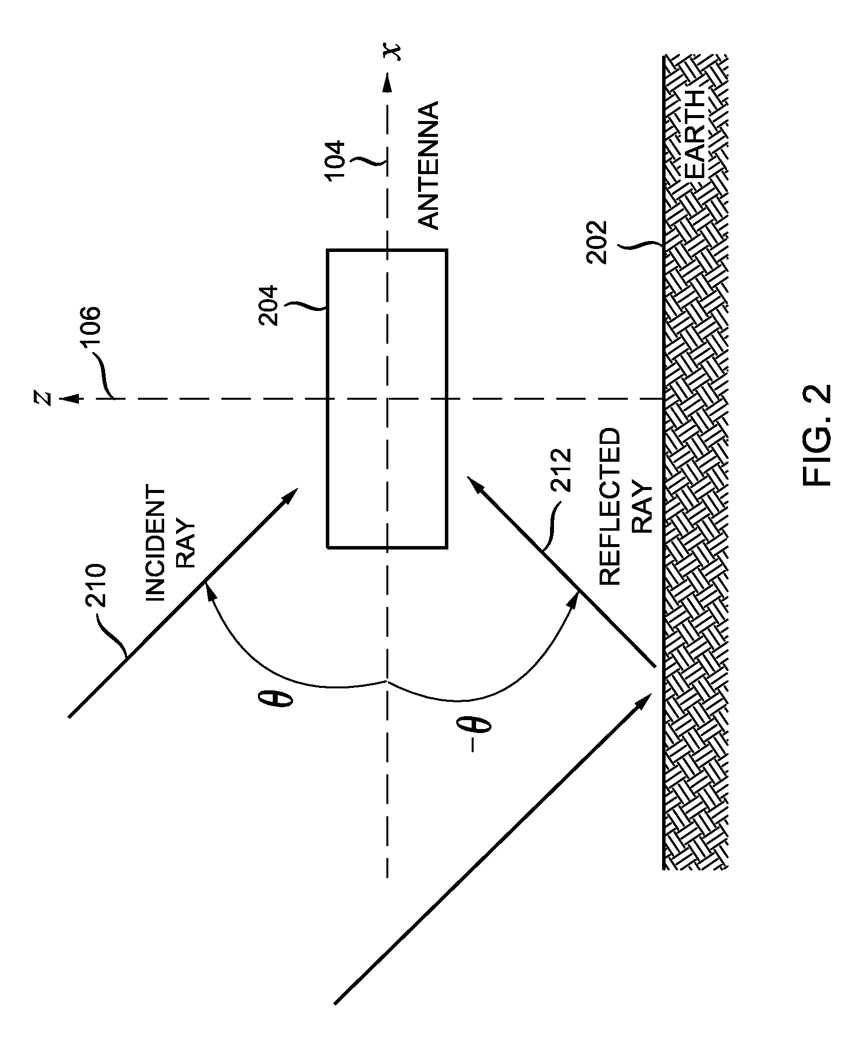
[0038]Since the polarization of the multipath signals are correlated with the polarization of the line-of-sight signals (as described in more detail below), multipath rejection capabilities of a ground plane can be characterized in terms of linear-polarized signals instead of circular-polarized signals. FIG. 1A and FIG. 1B show perspective views of a Cartesian coordinate system defined by the x-axis 102, y-axis 104, z-axis 106, and origin O 108. As shown in FIG. 1A, the magnetic field H-plane 120 lies in the y-z plane; as shown in FIG. 1B, the electric field E-plane 130 lies in the x-z plane. In the discussion below, modelling is performed with respect to the E-plane. Modelling with respect to the E-plane presents a worst-case scenario, since the multipath rejection capabilities of the antenna with respect to the H-plane are better than or equal to the multipath rejection capabilities of the antenna with respect to the E-plane.

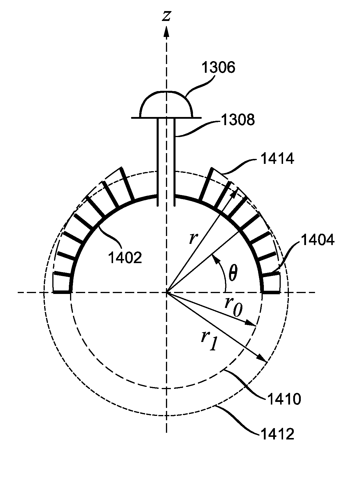
[0039]Geometric configurations are also described with r...


PUM


Abstract

A ground plane for reducing multipath reception comprises a convex conducting surface and an array of conducting elements disposed on at least a portion of the convex conducting surface. Embodiments of the convex conducting surface include a portion of a sphere and a sphere. Each conducting element comprises an elongated body structure having a transverse dimension and a length, wherein the transverse dimension is substantially less than the length. The cross-section of the elongated body structure can have various user-specified shapes. Each conducting element can further comprise a tip structure. The azimuth spacings, lengths, and surface densities of the conducting elements can be functions of meridian angle. An antenna can be mounted directly on the conducting convex surface or on a conducting or dielectric support structure mounted on the conducting convex surface. System components, such as a navigation receiver, can be mounted inside the conducting convex surface.

Description

[0001]This application claims the benefit of U.S. Provisional Application No. 61 / 225,367 filed Jul. 14, 2009, which is incorporated herein by reference.BACKGROUND OF THE INVENTION[0002]The present invention relates generally to antennas, and more particularly to broadband convex ground planes for multipath rejection.[0003]Multipath reception is a major source of positioning errors in global navigation satellite systems (GNSSs). Multipath reception refers to the reception by a navigation receiver of signal replicas caused by reflections from the receiver environment. The signals received by the antenna in the receiver are a combination of the line-of-sight (“true”) signal and multipath signals reflected from the underlying ground surface and surrounding objects and obstacles. Multipath reception adversely affects the operation of the entire navigation system. To mitigate multipath reception, the receiving antenna is commonly mounted onto a ground plane. Various types of ground planes...

Claims


Application Information

Patent Timeline
Patent Type & Authority Patents(United States)
IPC IPC(8): H01Q1/48
CPCH01Q15/16H01Q19/10H01Q15/0073H01Q19/021
Inventor TATARNIKOV, DMITRYASTAKHOV, ANDREYSTEPANENKO, ANTON
Owner TOPCON GPS
Learn More