Luminance enhancement structure with Moiré reducing design

a technology of enhancement structure and moiré reduction, applied in lighting and heating apparatus, lighting device details, instruments, etc., can solve the problems of significantly affecting the quality of images displayed, reducing brightness, and reducing brightness, so as to enhance the brightness of a display device, reduce the moiré effect, and enhance the effect of illumination enhancement structur

Active Publication Date: 2013-05-14
E INK CORPORATION
View PDF71 Cites 44 Cited by
  • Summary
  • Abstract
  • Description
  • Claims
  • Application Information

AI Technical Summary

Benefits of technology

[0005]The present invention is directed to a luminance enhancement structure which not only can enhance the brightness of a display device, but also can reduce the Moiré effect, regardless of the size and shape of the display cells in the display device. Moreover, the luminance enhancement structure of the present invention has the additional advantage that the brightness of the display device may change depending on the viewing angle, in a more uniform manner.

Problems solved by technology

The lack of satisfactory brightness is often a concern for electrophoretic display devices.
This total internal reflection phenomenon could result in a loss of about 30-50% of the scattering light, thus causing reduction in brightness.
However, when a luminance enhancement structure is applied onto an electrophoretic display, the Moiré effect may occur which could significantly affect the quality of the images displayed.
Such an approach obviously is not desirable because it could be costly.

Method used


Image

  • Luminance enhancement structure with Moiré reducing design
  • Luminance enhancement structure with Moiré reducing design
  • Luminance enhancement structure with Moiré reducing design

Examples


Embodiment Construction

I. Definitions

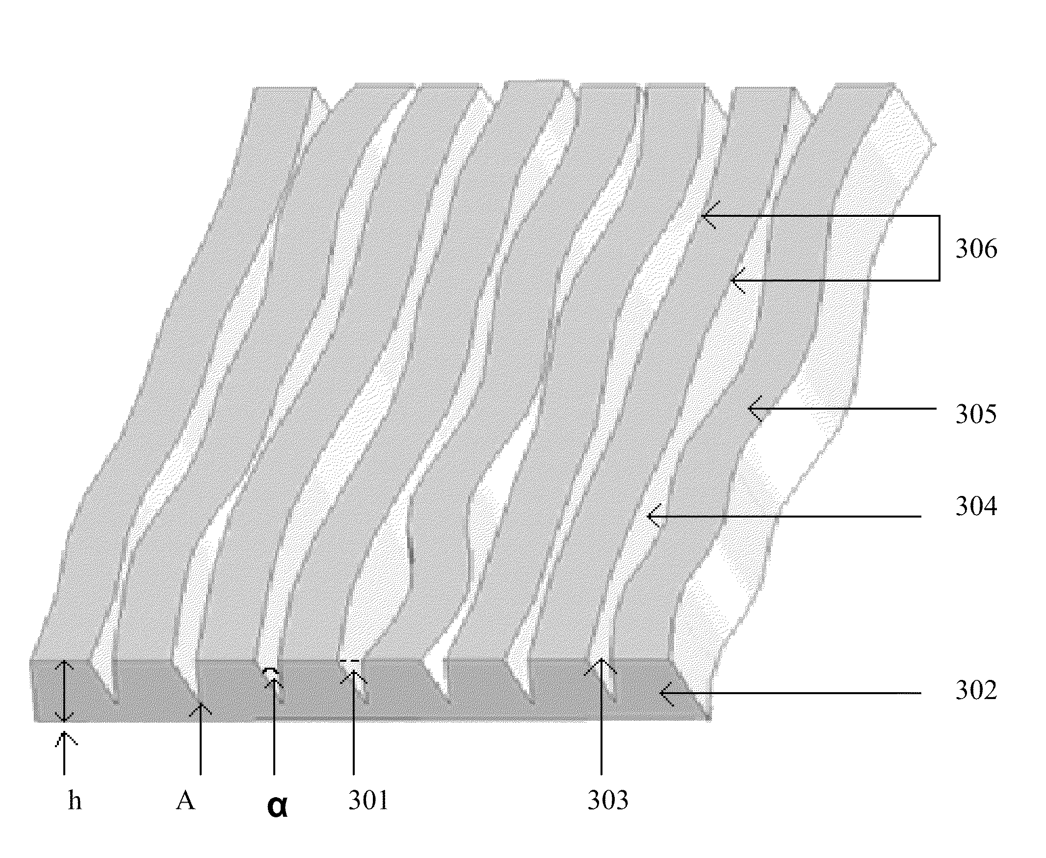
[0015]The technical term “total internal reflection” used in this application refers to an optical phenomenon that occurs when a ray of light strikes a medium boundary at an angle greater than the critical angle with respect to the normal axis to the surface. This can only occur where light travels from a medium with a higher refractive index to one with a lower refractive index.

[0016]Generally speaking, when a ray of light crosses a boundary between materials with different refractive indices, the light will be partially refracted at the boundary surface, and partially reflected. However, if the angle of incidence is greater than the critical angle, the light will stop crossing the boundary and instead be totally reflected back.

[0017]The critical angle is calculated based on the equation of Snell's law: C=sin−1(n2 / n1) wherein n1 and n2 are the refractive indices of the two different media, with n1 being the higher refractive index and n2 being the lower refractive ind...


PUM


Abstract

The present invention is directed to luminance enhancement structure for reflective display devices. The structure not only can enhance the brightness of a display device, but also can reduce the Moiré effect of the display device. The present invention is also directed to a display device comprising an array of microcups and a luminance enhancement structure.

Description

[0001]This application claims priority to U.S. Provisional Application No. 61 / 120,243, filed Dec. 5, 2008; the content of which is incorporated herein by reference in its entirety.FIELD OF THE INVENTION[0002]The present invention is directed to a luminance enhancement structure for reflective display devices. The structure not only can enhance the brightness of a display device; but also can reduce the Moiré pattern effect.BACKGROUND OF THE INVENTION[0003]The lack of satisfactory brightness is often a concern for electrophoretic display devices. Total internal reflection would occur with electrophoretic display devices due to the fact that the display device usually has components of a high refractive index. Because of the components having a higher refractive index (e.g., about 1.5) than the air (which has a refractive index of about 1) surrounding the display panel, some of the scattering light from the display panel may reflect back to the display device by total internal reflect...

Claims


Application Information

Patent Timeline
Patent Type & Authority Patents(United States)
IPC IPC(8): G09G3/16
CPCG02B5/045G02B17/006G02F2001/133507G02F1/133507
Inventor LIN, CRAIG
Owner E INK CORPORATION
Why Eureka
Try Eureka