System and apparatus for pixel matrix see-through display panels

a technology of pixel matrix and display panel, applied in the field of optical processing of display information and non-display information, can solve the problems of unattractive solutions for some applications, unsuitable for applications, large system,

Active Publication Date: 2013-05-14
INNOVEGA
View PDF54 Cites 112 Cited by
  • Summary
  • Abstract
  • Description
  • Claims
  • Application Information

AI Technical Summary

Benefits of technology

[0011]In some embodiments, the reflector is a polarization reflector. In additional embodiments, the reflector is a partial reflector. In yet further embodiments, the reflector has a concave shape which allows sufficient expansion of incident light rays to allow the incident light rays to pass around the pixel element. In some such embodiments, the concave shape reduces the expansion of incident light rays to parallel light rays perceivable by the human visual system.

Problems solved by technology

Current systems for optical processing of display information provided by a head-mounted display and non-display information provided by objects other than the head-mounted display may have characteristics that make them unattractive solutions for some applications.
Such systems tend to be large, bulky, and ill suited for applications where little space is available for processing the display information and the non-display information.
For example, such systems are unattractive solutions for processing display and non-display information in a fighter pilot's helmet where the space for the optical system is limited.

Method used


Image

  • System and apparatus for pixel matrix see-through display panels
  • System and apparatus for pixel matrix see-through display panels
  • System and apparatus for pixel matrix see-through display panels

Examples


Embodiment Construction

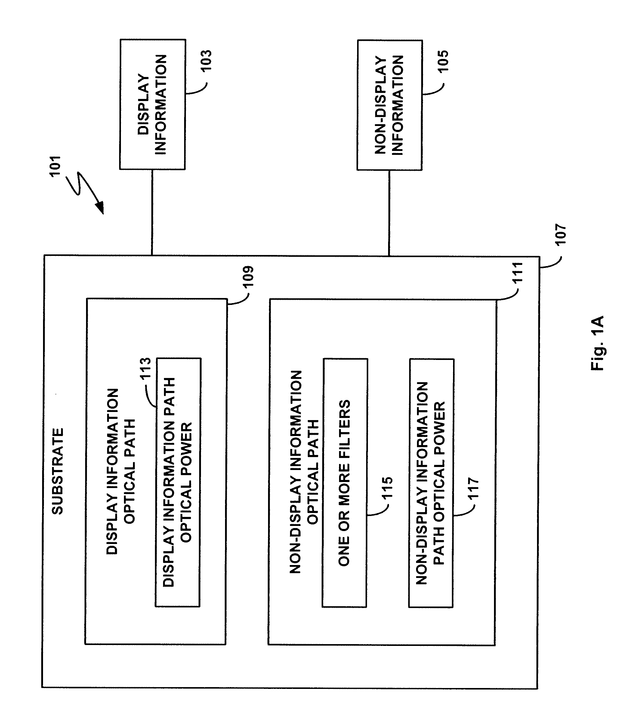
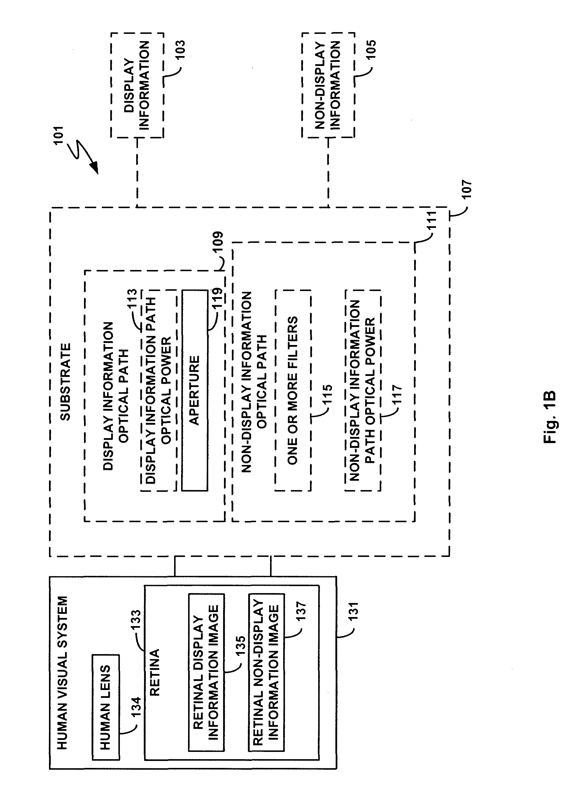
[0004]Various embodiments of the present invention provide for systems and apparatus directed toward using a display panel to process display information and non-display information. Further embodiments utilize a display panel in conjunction with a contact lens assembly configured to process the display information.

[0005]In one embodiment of the invention, a display panel assembly is provided, comprising: a transparent substrate that permits light to pass through substantially undistorted; a two-dimensional display panel disposed on the transparent substrate, wherein the display panel comprises pixel elements sufficiently spaced with respect to each other as to allow light to pass through the display panel assembly; and at least one filter disposed on at least one pixel element. The filter may be a bandpass filter that reduces bandwidths of emitted light from the at least one pixel element, or a polarizer filter that limits polarity of emitted light from the at least one pixel eleme...


PUM


Abstract

Various embodiments of the present invention provide systems and apparatus directed toward using a contact lens and deflection optics to process display information and non-display information. In one embodiment of the invention, a display panel assembly is provided, comprising: a transparent substrate that permits light to pass through substantially undistorted; a two-dimensional display panel disposed on the transparent substrate, wherein the display panel comprises pixel elements sufficiently spaced with respect to each other to allow light to pass through the display panel assembly; and at least one filter disposed on at least one pixel element. The filter may comprise a bandpass filter that reduces bandwidths of emitted light from the pixel element, or a polarizer filter that limits polarity of emitted light from the pixel element.

Description

RELATED APPLICATION[0001]This application is a continuation-in-part of and claims the benefit of U.S. patent application Ser. No. 12 / 204,567 filed Sep. 4, 2008, which is incorporated herein by reference in its entirety.FIELD OF THE INVENTION[0002]The present invention is related to optics and, more specifically, is directed toward optical processing of display information and non-display information using display panels and a dual path contact lens.DESCRIPTION OF THE RELATED ART[0003]Current systems for optical processing of display information provided by a head-mounted display and non-display information provided by objects other than the head-mounted display may have characteristics that make them unattractive solutions for some applications. The twin requirements of a large field of view and a comfortable Eyeto-system distance for the viewer results in multi-component optical systems where the final optical component has a large diameter. Such systems tend to be large, bulky, an...

Claims


Application Information

Patent Timeline
Patent Type & Authority Patents(United States)
IPC IPC(8): G02B27/10G02B27/14
CPCG02B27/0172G02C7/04G02C7/083G02C7/086G02C7/101G02C7/102G02C7/12G09G3/001G02B5/20G02B5/30G02B2027/0112
Inventor SPRAGUE, RANDALL
Owner INNOVEGA
Why Eureka
Try Eureka