Receiving device and method thereof

a technology of receiving device and receiving module, which is applied in the direction of direction finders using radio waves, transmission monitoring, radio wave direction/deviation determination systems, etc., can solve the problems of taking a lot of time to perform the above processes, and achieve the effects of saving a lot of time, increasing the detection speed and setting speed of the receiving module, and increasing the signal receiving and viewing quality

Active Publication Date: 2013-05-14
REALTEK SEMICON CORP
View PDF9 Cites 1 Cited by
  • Summary
  • Abstract
  • Description
  • Claims
  • Application Information

AI Technical Summary

Benefits of technology

[0006]In order to solve the above-mentioned problems, one object of the invention is to provide a receiving device that can quickly find out the direction having the optimum signal receiving quality.
[0009]The receiving device and the method thereof use the means of controlling settings of the internal circuits of the receiving module (sensing circuit) to have the receiving module only perform searching for the specific parameters while the receiving module scans for the signal of the channel. Thus, the optimum wireless signal of each channel can be found and the parameters of the optimum wireless signal are stored. When a user wants to view a different channel, the receiving module is instructed to automatically use the corresponding stored parameters of the channel to receive the optimum wireless signal so that the signal receiving and viewing quality can be increased. Since the receiving module only performs searching for the specific parameters, it can save a lot of time while performing signal detection, compared to the prior art that needs to do detection for all the parameters. Thus, the detection speed and setting speed of the receiving module can be increased to solve all the possible problems in the prior art.

Problems solved by technology

Therefore, it takes a lot of time to perform the above processes.

Method used


Image

  • Receiving device and method thereof
  • Receiving device and method thereof
  • Receiving device and method thereof

Examples


Embodiment Construction

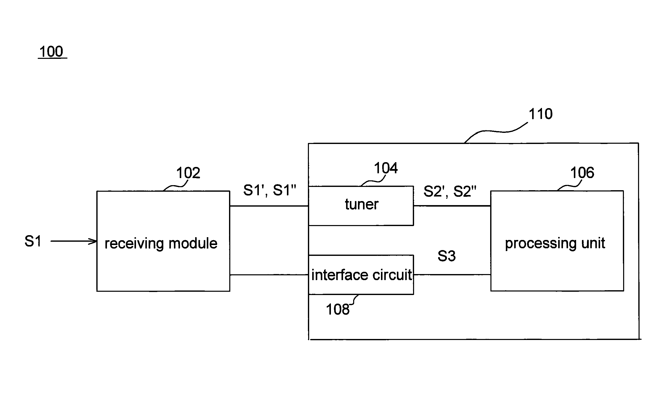
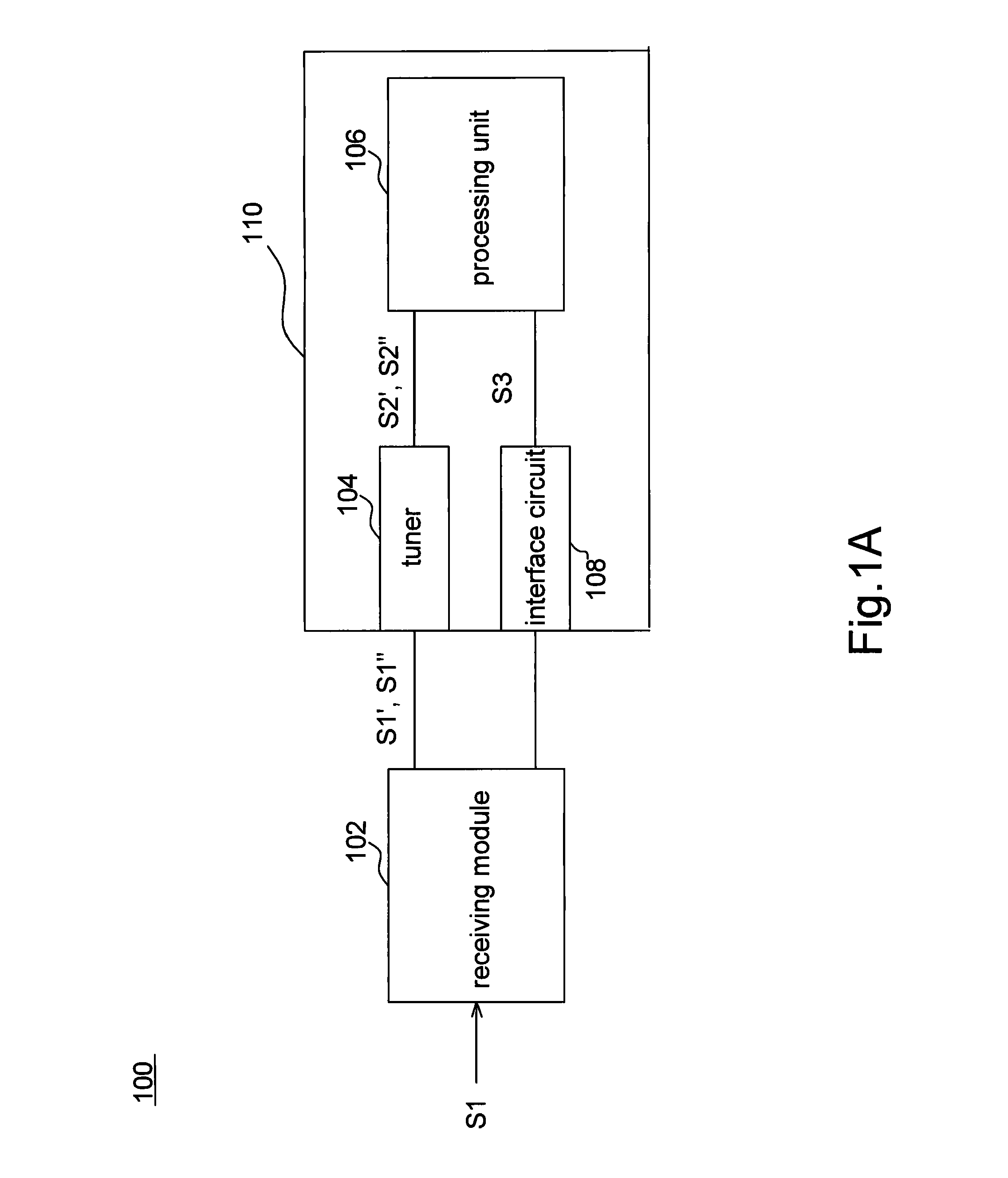
[0016]Please refer to FIG. 1A. FIG. 1A shows a schematic diagram illustrating a receiving device 100 according to one embodiment of the invention. The receiving device (or wireless signal receiving system or antenna processing system) 100 comprises a receiving module 102 and a processing module 110. The processing module 110 comprises a tuner 104, a processing unit 106, and an interface circuit 108.

[0017]The receiving module 102 comprises a plurality of parameters and is to set the parameters according to a control signal S3 and to receive a wireless signal S1 (for example, a radio-frequency signal) according to settings of the different parameters so as to output a first output signal S1′ and a second output signal S1″. In one embodiment, the receiving module 102 is an antenna or a sensing circuit. The parameters include at least one parameter or at least two parameters among a direction parameter, a gain parameter, and a polarity parameter.

[0018]The processing module 110 couples t...


PUM


Abstract

A receiving device is disclosed. The receiving device includes a receiving module and a processing module. The receiving module includes a plurality of parameters. The receiving module is used for setting the parameters according to a control signal, receiving a wireless signal according to settings of the different parameters, and outputting a first output signal and a second output signal separately. The processing module couples the receiving module and generates the control to set the parameters according the first output signal and the second output signal.

Description

BACKGROUND OF THE INVENTION[0001](a) Field of the Invention[0002]The invention relates to a communication system, particularly to a wireless communication system.[0003](b) Description of the Related Art[0004]In general, there are two ways for an antenna to receive a signal of a channel. One receiving method is to search signals in one direction like the commonly-used method by a fishbone antenna while the other receiving method is a complete signal searching method like reception by an electronic antenna.[0005]While a fishbone antenna is used to search in one direction for receiving a signal, the antenna will receive a signal of a channel in only one specific direction. However, actually the sources of channel signals are from all directions but not only one direction. Thus, as the direction of the signal is different from that of antenna reception, signal quality will decrease. As the electronic antenna searches signals for receiving, parameter detection will be performed on the co...

Claims


Application Information

Patent Timeline
Patent Type & Authority Patents(United States)
IPC IPC(8): H04B1/18H04M1/00
CPCH04B1/16G01S3/16
Inventor LO, JEN-CHIEHCHEN, YI-CHENGLAI, CHIA-TA
Owner REALTEK SEMICON CORP
Why Eureka
Try Eureka