Monitoring method for an elevator installation

a technology for installing safety circuits and monitoring methods, which is applied in the direction of computer control, instruments, and elevators, can solve problems such as the standstill of the elevator car, and achieve the effect of simple and reliable checking

Active Publication Date: 2013-05-21
INVENTIO AG
View PDF15 Cites 5 Cited by
  • Summary
  • Abstract
  • Description
  • Claims
  • Application Information

AI Technical Summary

Benefits of technology

[0014]The advantage of this monitoring method resides in the small data exchange between control unit and bus junction. Since the bus junction when the safety element is open, thus when, for example, a shaft door or a car door is open, communicates this potentially risky state to the control unit, a constant short-cyclic communication between control unit and bus junction is eliminated. As a consequence, use can be made of control units with lesser computing capacities as well as buses with smaller data transmission capacities, which leads to lower costs.
[0016]The advantage of these relatively long default and interrogation time intervals is a further relief of the bus between the control unit and the bus junctions function and a further reduction of the signals and data to be processed by the control unit.
[0018]The advantage of the spontaneous transmission of a digital signal by the transmitter to the control unit is based on the fact that the elevator can be safety operated notwithstanding relatively long default and interrogation intervals.
[0020]The advantage of this test procedure resides in the simple and reliable checking of the functional capability of a bus junction or of the spontaneous transmission behaviour of the transmitter. In this test procedure an open safety element is simulated and the corresponding spontaneous transmission behaviour of the transmitter provoked. The functional capability of the bus junction for normal operation is tested in every default-interrogation cycle.

Problems solved by technology

This has the consequence that a drive or brakes, which acts or act on the travel of an elevator car, brings the elevator car to a standstill.

Method used


Image

  • Monitoring method for an elevator installation
  • Monitoring method for an elevator installation
  • Monitoring method for an elevator installation

Examples


Embodiment Construction

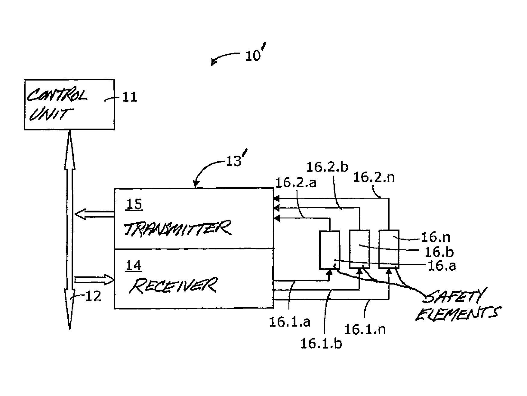
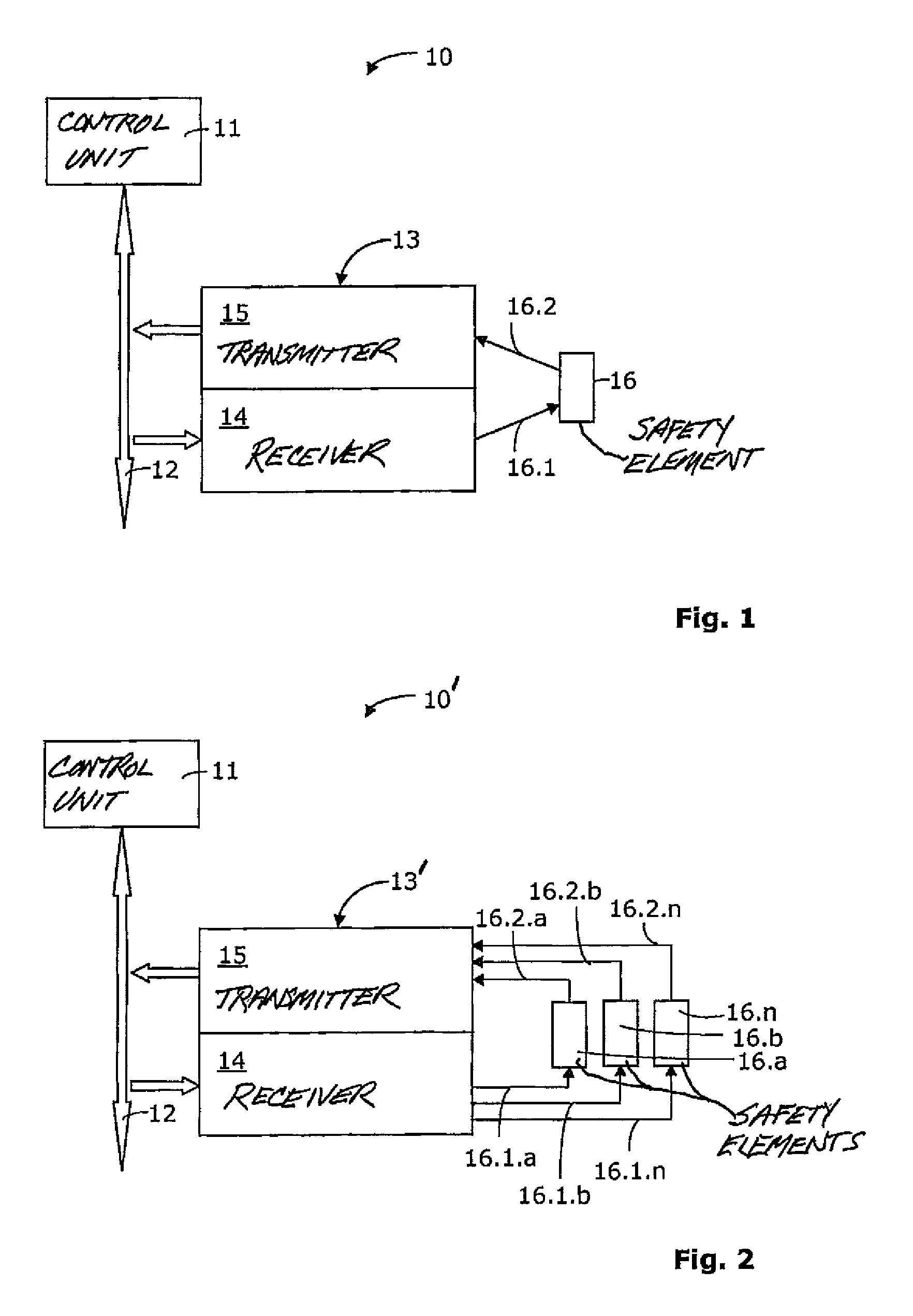
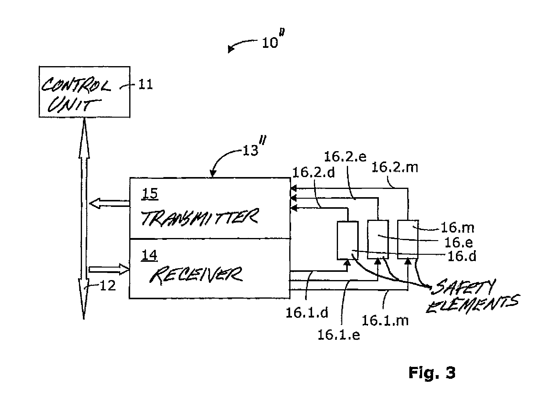
[0025]The present monitoring method is particularly suitable for elevator installations, as was described in the introduction. FIG. 1 shows a form of embodiment of a safety system 10 according to the invention which is technically adapted to perform the monitoring method. The safety system 10 has a control unit 11 and at least one bus junction 13. The communication between the control unit 11 and the bus junction 13 takes place by way of a bus 12. Data can thus be sent in both directions between the bus junction 13 and the control unit 11 by way of the bus. The bus junction 13 itself consists of a receiver 14, a transmitter 15 and a safety element 16. The receiver 14 and the transmitter 15, respectively, are each so designed that the former receives default signals from the control unit 11 and the latter provides status data as signals of the control unit 11.

[0026]The control unit 11, the bus 12 and the at least one bus junction 13 form a bus system. Within this bus system each bus ...


PUM


Abstract

The monitoring method for an elevator installation includes a control unit and at least one bus junction, which bus junction has a receiver, a transmitter and a safety element. The control unit and the bus junction communicate by way of a bus. The monitoring method has the following steps: a digital default signal is transmitted by the control unit to the receiver; the digital default signal is converted by the receiver into an analog signal; the safety element is acted on by the receiver with the analog signal; if the safety element is closed the analog signal is detected by the transmitter; for a detected analog signal, a digital signal of the control unit is provided by the transmitter; wherein on detection of an analog zero signal a digital signal is transmitted by the transmitter to the control unit.

Description

FIELD OF THE INVENTION[0001]The invention relates to a monitoring method for safety circuits of an elevator installation.BACKGROUND OF THE INVENTION[0002]Conventional elevator installations have safety circuits consisting of safety elements connected in series. These safety elements monitor, for example, the status of shaft or car doors. Such a safety element can be a contact. An open contact shows that, for example, a door is open and a potentially impermissible door state has occurred. If, now, with the contact opened an impermissible open state of the door is identified then the safety circuit is interrupted. This has the consequence that a drive or brakes, which acts or act on the travel of an elevator car, brings the elevator car to a standstill.[0003]A safety system for an elevator installation is known from the PCT patent specification WO2005 / 000727, which comprises a control unit as well as at least one bus junction and bus. The bus enables communication between the bus junc...

Claims


Application Information

Patent Timeline
Patent Type & Authority Patents(United States)
IPC IPC(8): B66B1/28
CPCB66B13/22B66B5/0093
Inventor SONNENMOSER, ASTRIDHEINZ, KURT
Owner INVENTIO AG
Why Eureka
Try Eureka