
Lamp holder structure with universal accommodating slot

a technology of lamp holder and universal housing, which is applied in the direction of electrical discharge lamps, lighting and heating apparatus, coupling device connections, etc., can solve the problems of increasing the number of components, increasing the cost of assembling, and increasing the complexity of the assembling procedure of the lamp holder structure, so as to reduce the quantity of components and simplify the assembling procedure significantly, without increasing production lines

Inactive Publication Date: 2013-05-21
CHEN TSAN CHI
View PDF1 Cites 0 Cited by
  • Summary
  • Abstract
  • Description
  • Claims
  • Application Information

AI Technical Summary

Benefits of technology

The present invention provides a method for manufacturers to quickly and easily install different types of pressing elements into a universal accommodating slot of a lamp holder structure. This method reduces the amount of components needed and simplifies the assembly process. It also lowers the manufacturing and assembly costs associated with conventional lamp holder structures which require expensive rotating axial devices, push lever devices, or stringer bead wheel devices. This simplifies the design of the lamp holder structure and allows for mass production of different models without the need for additional production lines.

Problems solved by technology

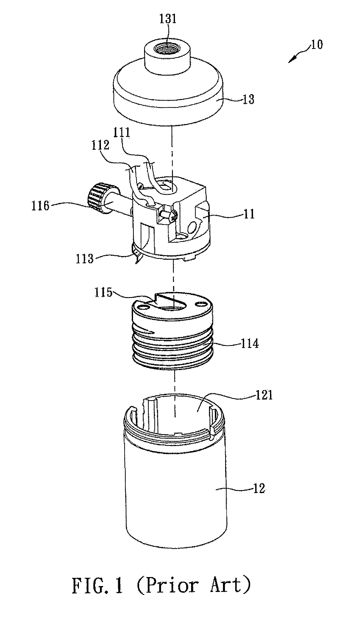
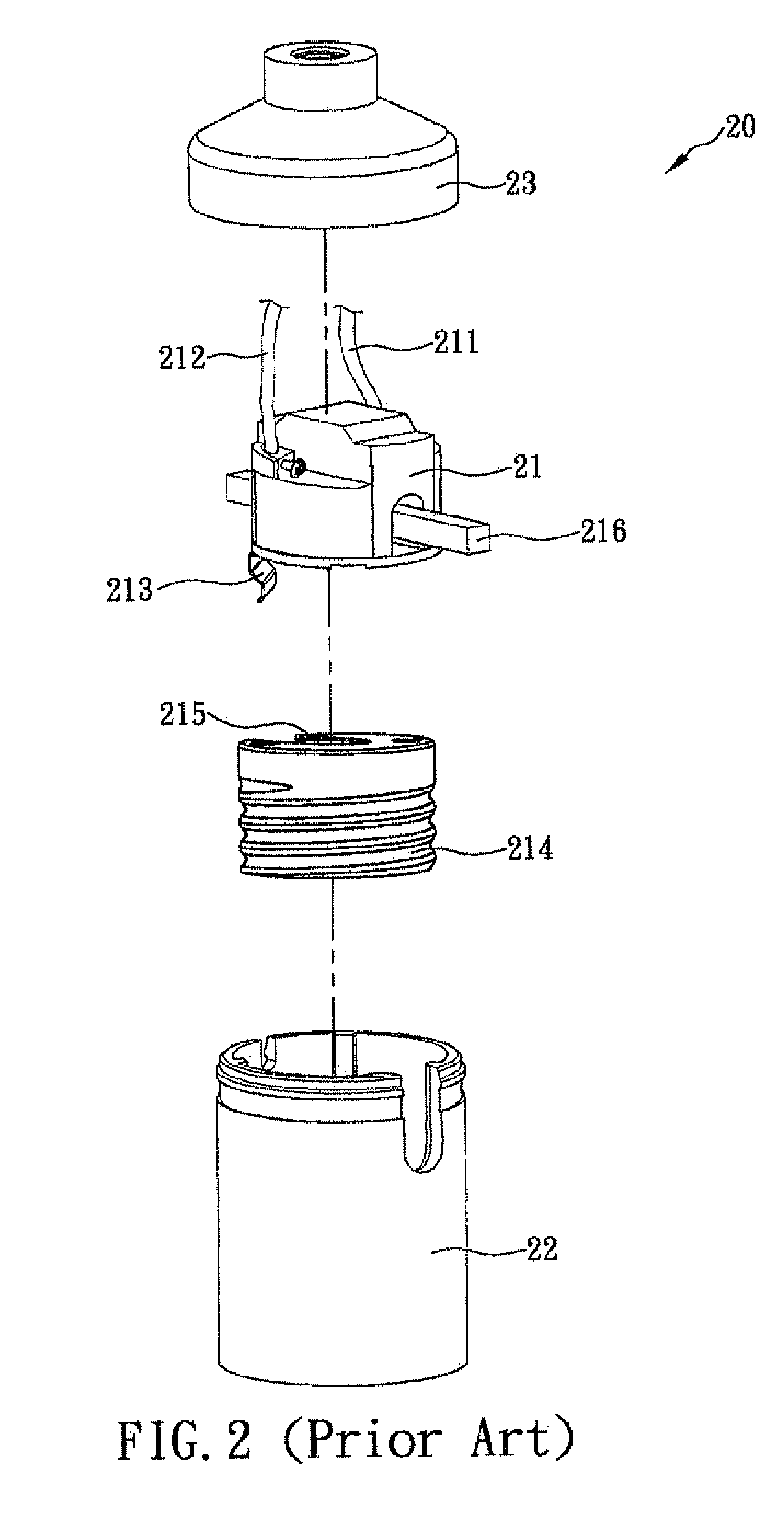
Although the use of the aforementioned conventional lamp holder structures 10, 20, 30 are convenient, their actual manufacture still has problems.
As a result, the manufacturers have to purchase more components and waste unnecessary expenses and assembling time.
Obviously, the assembling procedure of the lamp holder structure becomes more complicated.
As the market demand for the lamp holder structure of a certain specification rises drastically and the market demand for the lamp holder structure of other specifications drops drastically, the manufacturers have to increase the number of product lines for the lamp holder structure of one specification and decrease the number of production lines for the lamp holder structure of the other specification, and thus making the production management more complicated, and causing a delay of production schedule easily.
Furthermore, the manufacturers have to make the molds in advance or purchase the expensive and complicated rotating axial device 11, push lever device 21 or stringer bead wheel device 31, and then install these components to the conventional lamp holder structure 10, 20, 30, so that the production cost for the manufacture and assembling of the components of the conventional lamp holder structure 10, 20, 30 must be increased, and the increase of the cost is definitely an unfavorable factor to the manufacturers.

Method used


Image

  • Lamp holder structure with universal accommodating slot
  • Lamp holder structure with universal accommodating slot
  • Lamp holder structure with universal accommodating slot

Examples


Embodiment Construction

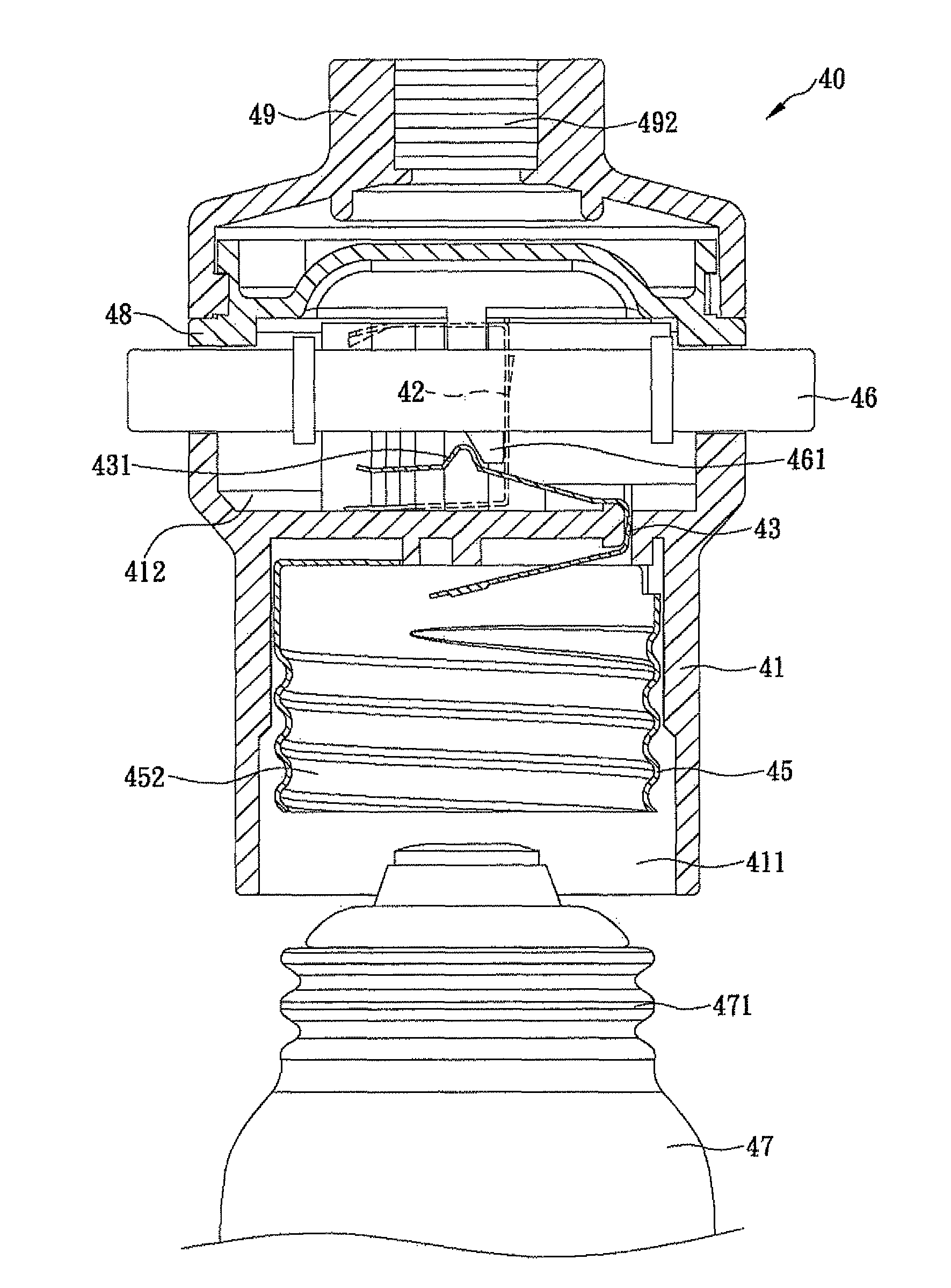
[0019]With reference to FIGS. 4 and 5 for a lamp holder structure with a universal accommodating slot in accordance with a first preferred embodiment of the present invention, the lamp holder structure 40 comprises a main body 41, a first electrically conductive plate 42, a metal spring plate 43, a second electrically conductive plate 44, a lamp holder base 45 and a pressing element 46, wherein an accommodating space 411 is concavely formed at the bottom of the main body 41, and a universal accommodating slot 412 is concavely formed at the top of the main body 41. The first electrically conductive plate 42 is installed at the top of the main body 41 and a position proximate to the universal accommodating slot 412, and an end of the first electrically conductive plate 42 is extended to the bottom of the universal accommodating slot 412, and the other end the universal accommodating slot 412 is electrically coupled to a first electric wire 413. The metal spring plate 43 is embedded in...


PUM


Abstract

The present invention relates to a lamp holder structure comprising a main body having a universal accommodating slot and an accommodating space concavely formed at the top and the bottom of the main body respectively, and a first electrically conductive plate and a second electrically conductive plate both installed at the top of the main body proximate to the universal accommodating slot, wherein the second electrically conductive plate is electrically coupled with a lamp holder base contained in the accommodating space, a metal spring plate is embedded into the main body, and a pressing element is contained in the universal accommodating slot and can be rotated or moved back and forth in the universal accommodating slot for pressing against a flange of the metal spring plate, such that the metal spring plate can be electrically coupled to or detached from the first electrically conductive plate.

Description

FIELD OF THE INVENTION[0001]The present invention relates to a lamp holder structure comprising a main body having a universal accommodating slot and an accommodating space concavely formed at the top and the bottom of the main body respectively, and a first electrically conductive plate and a second electrically conductive plate both installed at the top of the main body proximate to the universal accommodating slot, wherein the second electrically conductive plate is electrically coupled with a lamp holder base contained in the accommodating space, a metal spring plate is embedded into the main body, and a pressing element is contained in the universal accommodating slot and can be rotated or moved back and forth in the universal accommodating slot for pressing against a flange of the metal spring plate, such that the metal spring plate can be electrically coupled to or detached from the first electrically conductive plate. Since the design of the lamp holder structure of the pres...

Claims


Application Information

Patent Timeline
Patent Type & Authority Patents(United States)
IPC IPC(8): H01R33/00
CPCH01R33/962
Inventor CHEN, TSAN-CHI
Owner CHEN TSAN CHI
Learn More