
Extruder with non-stop die change device and method of using same

a technology of die change device and extruder, which is applied in the field of food and feeds, can solve the problems of long process time, low operation efficiency of extruder, and long time-consuming for die change devices and varieties of products

Active Publication Date: 2021-11-23
FAMSUN CO LTD
View PDF11 Cites 0 Cited by
  • Summary
  • Abstract
  • Description
  • Claims
  • Application Information

AI Technical Summary

Benefits of technology

The invention is a new extruder that solves problems in the prior art by allowing for non-stop changing of dies without stopping the extruder. This improves production efficiency and reduces production downtime. Additionally, the invention solves issues of pollution and granule adhesion caused by water vapor. The invention also helps avoid adhered granules and reduces the amount of residual water vapor in the environment.

Problems solved by technology

For example, the extruders have low operation efficiency, where changing dies and varieties of products take a long time.
Such a process takes a long time, generally 30 to 60 minutes.
If the operator is unskilled, the time for changing the product may take 120 minutes or more.
In addition to the varieties of products, the die of the extruder is often blocked by fibers and impurities in the raw materials during the production process.
A quite long time is taken.
Due to the above factors, the efficiency of the effective operation of the extruder is quite low.
This challenge with the need to solve the problem is that the rapid die change requires a rapid knife hood change and both knife hoods are necessary when a product is flowing through both dies simultaneously.
Therefore, a heretofore unaddressed need exists in the art to address the aforementioned deficiencies and inadequacies.

Method used


Image

  • Extruder with non-stop die change device and method of using same
  • Extruder with non-stop die change device and method of using same
  • Extruder with non-stop die change device and method of using same

Examples


embodiment 1

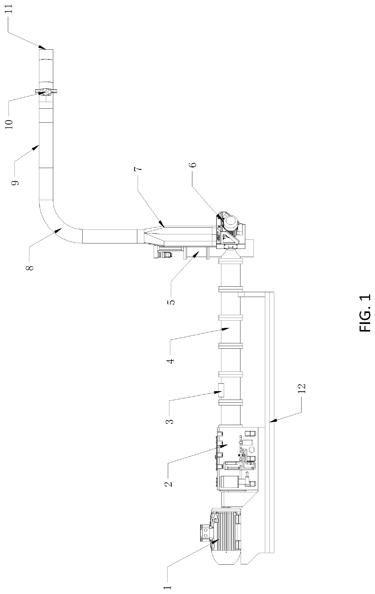
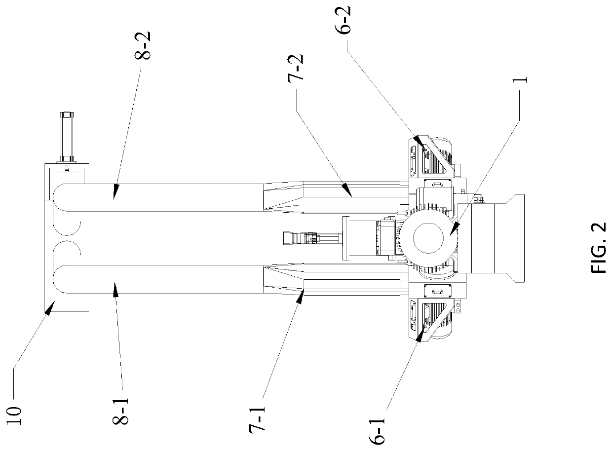
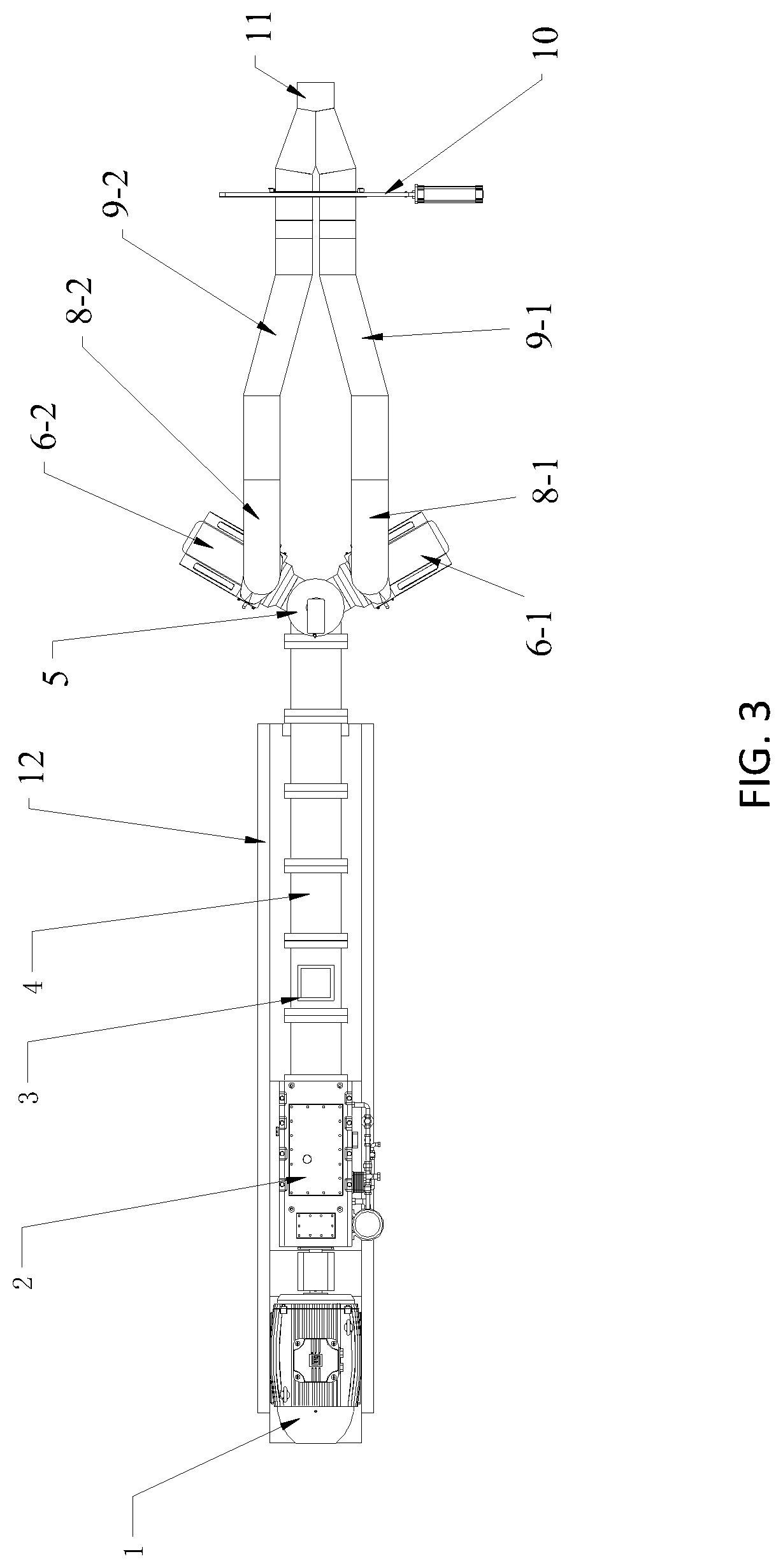
[0081]FIGS. 1-21 show a first embodiment (i.e., Embodiment 1) of an extruder with the non-stop die change device according to the invention.

[0082]Referring to FIGS. 1-14, in Embodiment 1, an extruder includes a base 12 for supporting the entire extruder, and a motor 1 directly connected with the base 12. The motor is directly connected with a gearbox 2. The gearbox 2 is connected with a long housing-shaped multi-section extrusion cavity 4. A feed extrusion cavity 3 is provided near the start position of the extrusion cavity. A conveyor in the feed extrusion cavity 3 is a screw rod 13, and the gearbox 2 and the motor 1 drive the screw rod to rotate. The tail end of the extrusion cavity is connected with a die change mechanism 5, which includes two dies: a die A 17-1 and a die B 17-2. The die A and the die B are connected with a cutting device A 6-1 and a cutting device B 6-2, respectively.

[0083]The cutting device A 6-1 is connected with a sealed vertical air duct 7-1 installed at the...

embodiment 2

[0180]FIGS. 22-33 show a second embodiment (i.e., Embodiment 2) of an extruder with the non-stop die change device according to the invention.

[0181]Referring to FIGS. 22-27, in Embodiment 2, an extruder includes a base 10 for supporting the entire extruder, and a motor 1 directly connected with the base 10, wherein the motor is directly connected with a gearbox 2, the gearbox 2 is connected with a long housing-shaped multi-section extrusion cavity 4, and a feed extrusion cavity 3 is provided near the start position of the extrusion cavity. The tail end of the extrusion cavity is connected with a die change device 5, which includes two dies: a die A 15-1 and a die B 15-2. The die A and the die B are connected with a cutting device A 6-1 and a cutting device B 6-2, respectively.

[0182]The cutting device A 6-1 is connected with a sealed vertical air duct 7-1 installed at the upper part thereof, then the vertical air duct 7-1 is connected with a bend 8-1, and the bend 8-1 is connected wi...


PUM


Abstract

An extruder with a non-stop die change device includes an extrusion cavity, a die change device located at the outlet of the extrusion cavity, and a first die and a second die that are connected to the side wall of a housing of the die change device. A transfer channel is provided in a movable block of the die change device. When the movable block moves to a first position in the housing, the transfer channel communicates to the extrusion cavity with a first channel, and when the movable block moves to a second position in the housing, the transfer channel communicates to the extrusion cavity with a second channel. Therefore, die change and product type change can be achieved without stopping the extruder. If a die is blocked, the extruder does not need to stop for changing a new die.

Description

CROSS-REFERENCE TO RELATED APPLICATIONS[0001]This application is a continuation application of International Patent Application No. PCT / CN2017 / 099624, filed Aug. 30, 2017, which itself claims the priority to Chinese Patent Application Nos. CN201710329050.8 and CN201710329046.1, both filed May 11, 2017 in the State Intellectual Property Office of P.R. China, which are hereby incorporated herein in their entireties by reference.FIELD OF THE INVENTION[0002]The invention relates generally to the field of food and feeds, and more particularly, to an extruder with a non-stop die change device and a method of using the same for processing pet food, human food and aquatic feeds.BACKGROUND OF THE INVENTION[0003]The background description provided herein is for the purpose of generally presenting the context of the invention and is neither expressly nor impliedly admitted as prior art against the invention. The subject matter discussed in the background of the invention section should not be ...

Claims


Application Information

Patent Timeline
Patent Type & Authority Patents(United States)
IPC IPC(8): A23P30/20A23P30/34
CPCA23P30/20A23P30/34A23N17/00
Inventor STRATHMAN, ROBERT TIMOTHYMA, LIANGAN, ZHE
Owner FAMSUN CO LTD
Learn More