Two gang electrical box for rapid mounting using hole saw

a technology of hole sawing and electrical boxes, applied in the field of electrical boxes, can solve the problems of high installation cost of additional electrical services, and achieve the effect of reducing the amount of time required for mounting

Active Publication Date: 2013-05-21
ARLINGTON INDS
View PDF10 Cites 36 Cited by
  • Summary
  • Abstract
  • Description
  • Claims
  • Application Information

AI Technical Summary

Benefits of technology

[0015](8) The electrical mounting device of the present invention significantly reduces the amount of time required for mounting an electrical device to a wall.
[0016

Problems solved by technology

One problem with this method is that the homeowner must make a hole large enough to accommodate the flip out clamps that extend outward from the sidewalls of the electr

Method used


Image

  • Two gang electrical box for rapid mounting using hole saw
  • Two gang electrical box for rapid mounting using hole saw
  • Two gang electrical box for rapid mounting using hole saw

Examples


first embodiment

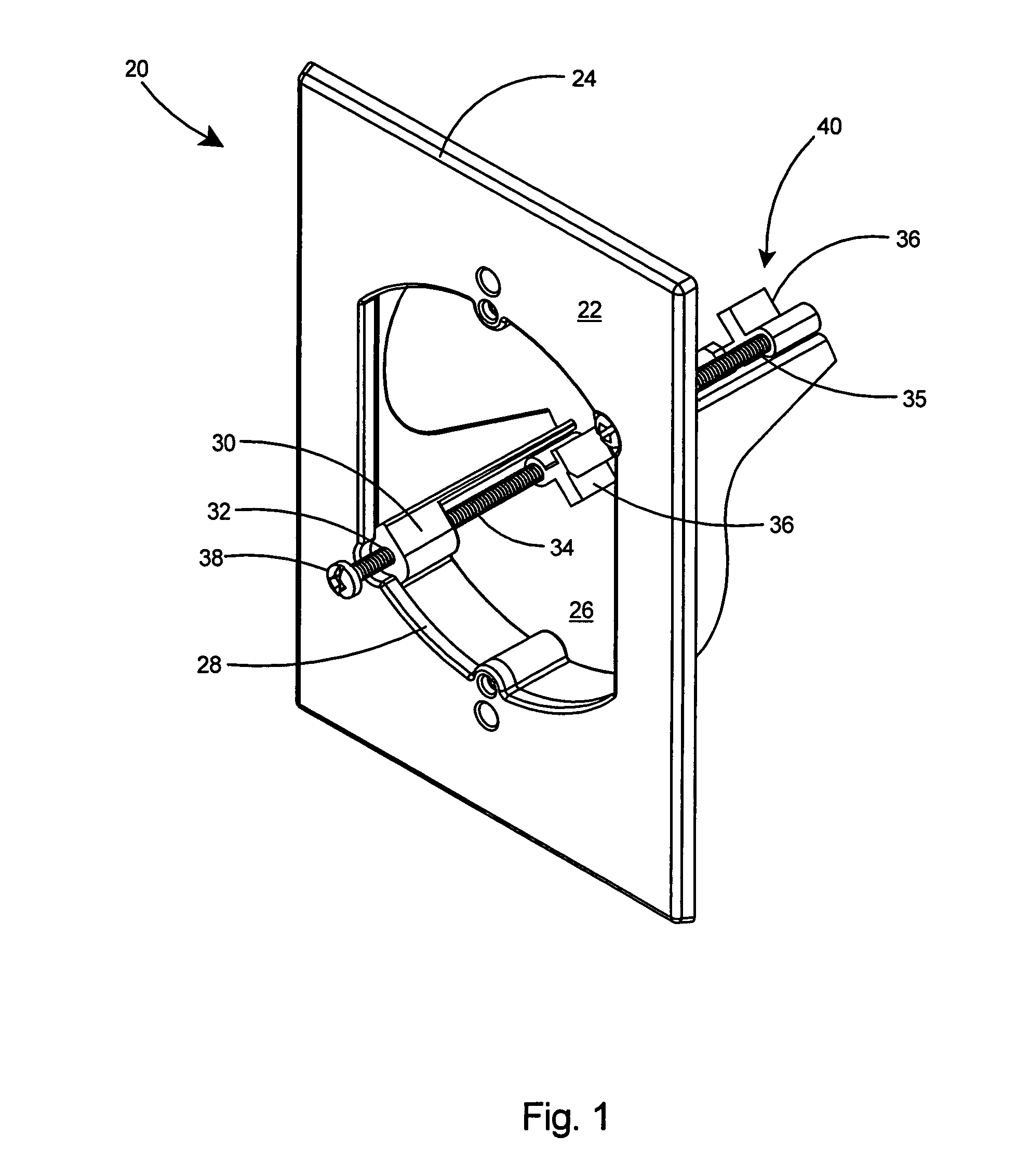
[0136]As shown in FIG. 1, an electrical mounting device 20 according to the present invention includes a front plate 22 having a contoured periphery 24 and an opening 26 with an inner periphery 28. Two mounting bosses 30, integral with the plate 22, are provided along the inner periphery 28. The mounting bosses 30 include oversize apertures 32 therein. Substantially long mounting fasteners 34 include ends 35 that extend through the oversize apertures 32 in the mounting bosses 30 and each mounting fastener 34 includes a clamp arm 36 secured rigidly to the end 35 of the fastener 34. Thus each mounting fastener 34 can be easily rotated within its oversize aperture 32 as desired by turning the head 38 of the respective fastener 34 with an appropriate tool such as a screwdriver (not shown). Each clamp arm 36 can therefore be rotated between an extended position and retracted position 40 as desired. FIG. 1 depicts the clamp arms 36 in the retracted position 40.

[0137]With reference to FIGS...

second embodiment

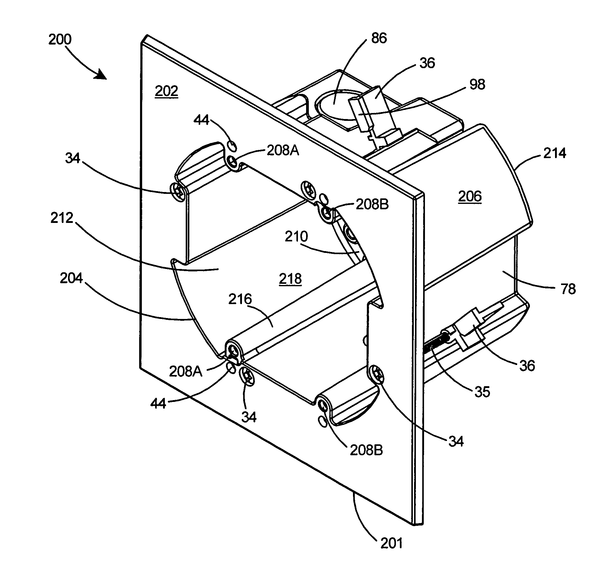
[0144]Referring to FIGS. 18 and 19, when in the retracted position 40, the clamp arms 36 are recessed within the recessed area 78 of the sidewall 48. the electrical mounting device 70 includes a second edge 94 which will serve to stop the clockwise advancement of the mounting fastener 34 and position the clamp arm 36 in the extended position (not shown). The shallow recess 82 in the sidewall 48 of the electrical box 74 can include an electrical fitting 96 therein that has been inserted in a knockout aperture 86. An electrical fitting 96 such as the “BLACK BUTTON™” connector available from Arlington Industries, Inc., of Scranton, Pa., can be inserted within the aperture, frictionally held therein as shown. The “BLACK BUTTON™” connector is disclosed in U.S. Pat. No. 5,693,910, the entire contents of which are incorporated herein by reference.

[0145]With reference to FIGS. 20 and 21, the sidewall 48 of the electrical box 74 including circular wall portion 84 and recessed areas 78 are co...


PUM


Abstract

A two gang electrical box that greatly reduces the time and effort required to mount one or two electrical components to a wall or similar surface. Wall preparation requires only the use of a standard hole saw thereby greatly minimizing installation time. The two gang electrical box includes a plate with an opening therein and a substantially circular sidewall extending from the plate at the periphery of the opening and terminating in a rear wall. Mounting fasteners extending through the plate include clamp arms thereon for securing the electrical box to a wall. The clamp arms can be rotated to either an inward position or an outward position. The sidewall is provided with open areas or recesses to fully accommodate the clamp arms when rotated to the inward position thereby enabling the peripheral wall and clamp arms to pass easily within the wall opening created by the standard size hole-saw.

Description

[0001]This application is a Continuation-In-Part of U.S. patent application Ser. No. 12 / 319,648 filed Jan. 9, 2009 now U.S. Pat. No. 8,063,302, which is a Continuation-In-Part of U.S. patent application Ser. No. 12 / 012,907 filed Feb. 6, 2008 and now U.S. Pat. No. 7,759,576, which is also a Continuation-In-Part of U.S. patent application Ser. No. 12 / 008,120 filed Jan. 9, 2008 and now U.S. Pat. No. 7,586,039, all of which are incorporated herein in their entireties by reference thereto.FIELD OF THE INVENTION[0002]This invention relates to electrical boxes for mounting one or more high or low voltage electrical components or a light fixture to a wall and specifically to an electrical box or frame member with retractable clamp arms for rapid mounting to a wall through a round aperture.BACKGROUND OF THE INVENTION[0003]To improve the lighting or electrical services in their homes, homeowners frequently retrofit their homes with additional electrical devices or light fixtures. Typically th...

Claims


Application Information

Patent Timeline
IPC IPC(8): H01H9/02
CPCH02G3/123Y10S248/906
Inventor GRETZ, THOMAS J.
Owner ARLINGTON INDS
Why Eureka
Try Eureka