Wireless power transmission system

a power transmission system and wireless technology, applied in the direction of program control, testing/monitoring control system, instruments, etc., can solve the problems of waste of power transmission, low efficiency of solar cells, heat dissipation, etc., and achieve the effect of minimizing backscatter

Active Publication Date: 2013-05-21
OSSIA
View PDF43 Cites 295 Cited by
  • Summary
  • Abstract
  • Description
  • Claims
  • Application Information

AI Technical Summary

Problems solved by technology

While solar-powered battery chargers are known, solar cells are expensive, and a large array of solar cells may be required to charge a battery of any significant capacity.
However, there are several problems associated with the efficient delivery of power by microwave transmission that have precluded the use of dedicated terrestrial microwave power transmitters for the purpose.
Such power transmission is wasteful, as most of the energy would be transmitted and not received by the intended devices, it could be hazardous to living tissue, it would most likely interfere with most electronic devices in the immediate vicinity, and it may be dissipated as heat.
Utilizing a directional antenna has several challenges, some of which are: knowing where to point it; the mechanical devices needed to track it would be noisy and unreliable; and creating interference for devices in the line of sight of the transmission.
However, even when the device is located, efficient transmission is not guaranteed due to reflections and interference of objects in the vicinity of the receiving device.

Method used


Image

  • Wireless power transmission system
  • Wireless power transmission system
  • Wireless power transmission system

Examples


first embodiment

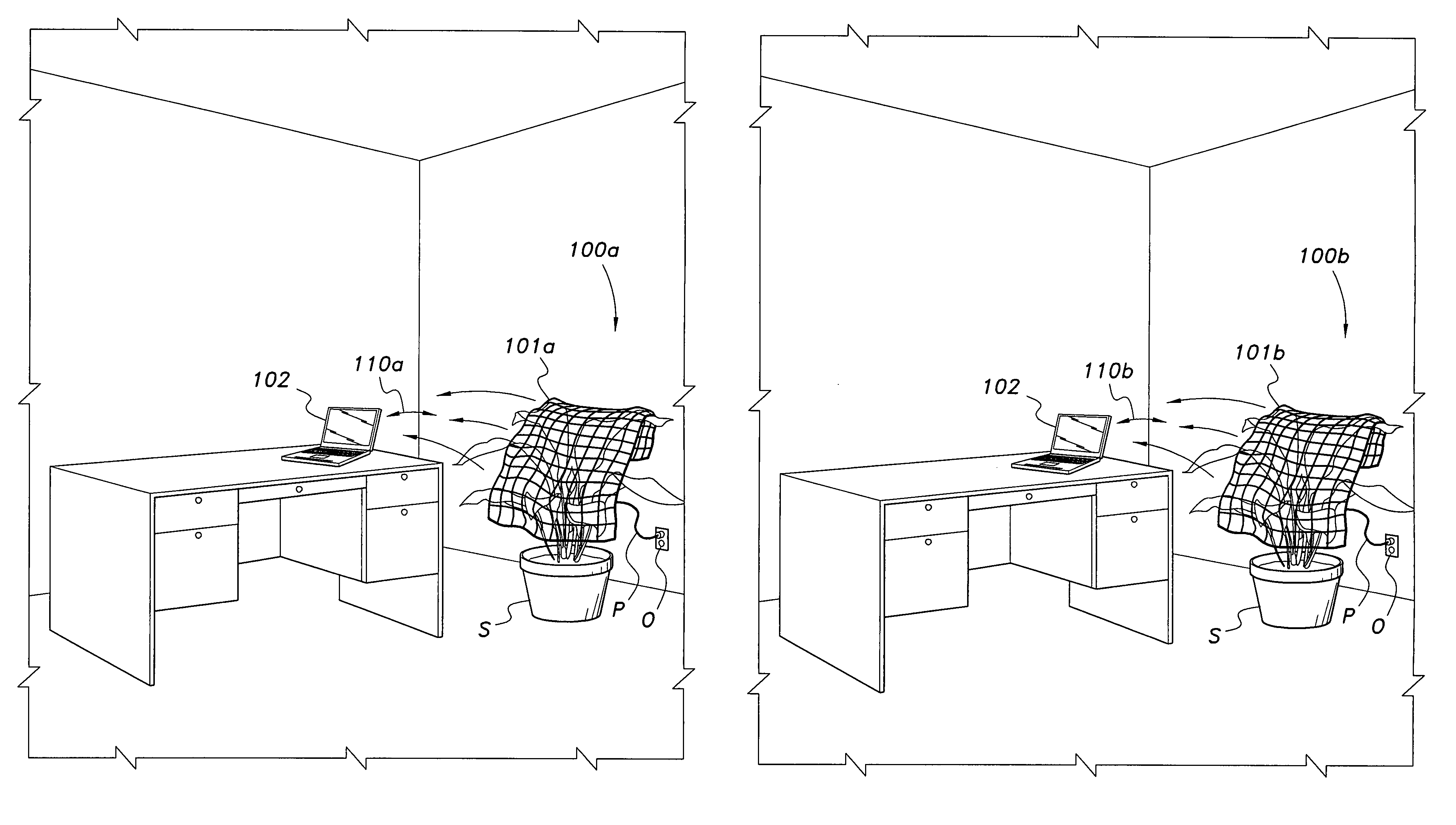
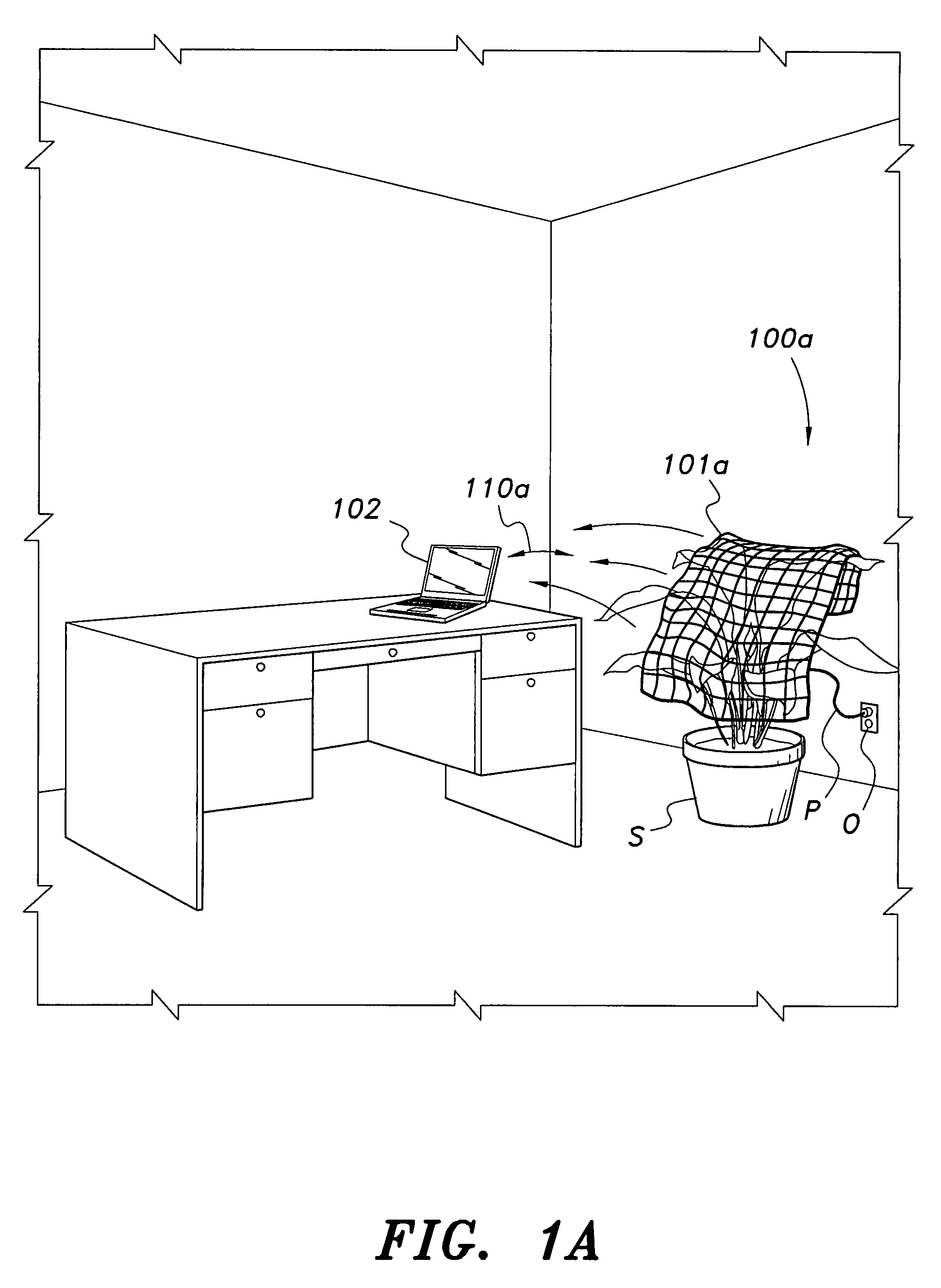
[0025]As shown in FIGS. 1A-3B, the microwave energy is focused onto a device to be charged by a power source 300 connected to one or more adaptively-phased microwave array emitters 204, i.e., antennae or radiators. According to the present invention, the microwave energy from the adaptively-phased microwave array emitters 204 may be focused onto the device without the need to know the location of the device. As shown in FIGS. 1A, 1B, and 3A-3B, preferably highly efficient rectennas 340 (a rectenna is a rectifying antenna that converts microwave energy directly into d.c. electricity; such devices are known in the art and will not be described further herein) within the device to be charged 102 receive and rectify the microwave energy and use it for charging battery 370 via charging and / or for primary power to the device 102 as determined by control logic 350. In a first embodiment, a communications channel is opened between the wireless power source 100a and power receiver 330b in th...

second embodiment

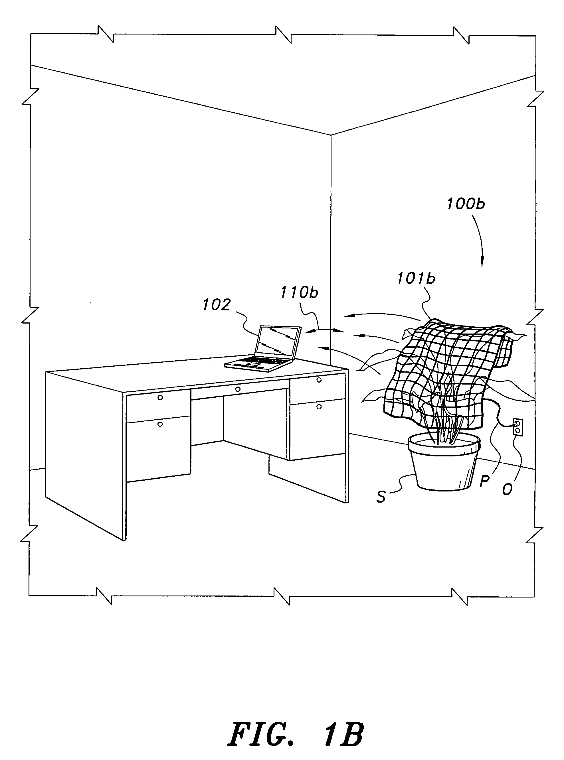
[0030]In a second embodiment, as most clearly shown in FIGS. 2B and 3B, each array element or node 204 can be set to receive a calibration signal from a calibration transmitter 460 in the power receiving system 330b. Each array element or node 204 can send the received calibration signal detected at that node 204 to the control logic 310 via data line 303. Subsequently, either controller 310, controller 206, or both controllers in combination may set each array element or node 204 to the detected phase for that element as a transmitting phase in order to send an optimized power beam 301 back to the power receiver 330b. In both embodiments 100a and 100b, a configuration memory device may be in operable communication with the controller logic 310 in order to enable the array to transmit power to a specific location or “hotspot” without first having to communicate to the device to be charged 102. This feature is useful in sending power beam 301 to the device to be charged 102 when the ...


PUM


Abstract

The wireless power transmission is a system for providing wireless charging and / or primary power to electronic / electrical devices via microwave energy. The microwave energy is focused onto a device to be charged by a power transmitter having one or more adaptively-phased microwave array emitters. Rectennas within the device to be charged receive and rectify the microwave energy and use it for battery charging and / or for primary power. A communications channel is opened between the wireless power source and the device to be charged. The device to be charged reports to the power source via the channel a received beam signal strength at the rectennas. This information is used by the system to adjust the transmitting phases of the microwave array emitters until a maximum microwave energy is reported by the device to be charged. Backscatter is minimized by physically configuring the microwave array emitters in a substantially non-uniform, non-coplanar manner.

Description

BACKGROUND OF THE INVENTION[0001]1. Field of the Invention[0002]The present invention relates generally to power transmission systems and battery chargers, and particularly to a method and system for wireless power transmission by microwave transmission to power a device requiring electrical power.[0003]2. Description of the Related Art[0004]Many portable electronic devices are powered by batteries. Rechargeable batteries are often used to avoid the cost of replacing conventional dry-cell batteries, and to conserve precious resources. However, recharging batteries with conventional rechargeable battery chargers requires access to an a.c. power outlet, which is sometimes not available. It would therefore be desirable to derive power for a battery charger from electromagnetic radiation.[0005]While solar-powered battery chargers are known, solar cells are expensive, and a large array of solar cells may be required to charge a battery of any significant capacity. Another potential sourc...

Claims


Application Information

Patent Timeline
Patent Type & Authority Patents(United States)
IPC IPC(8): G05B19/00H04Q9/00G05B23/00G06F7/00G06F7/04G08B29/00G08B1/00G08C19/00H04Q1/00H04B1/00H04B3/00
CPCH02J17/00H02J7/007H02J50/23H02J50/80H02J50/402H02J50/27H02J50/90H02J50/40H04B5/0037H02J50/005H02J50/20
Inventor ZEINE, HATEM
Owner OSSIA
Why Eureka
Try Eureka