Hydraulic circuit adapted for coupling motors

a coupling motor and hydraulic circuit technology, applied in the direction of couplings, belts/chains/gearings, couplings, etc., can solve the problems of low efficiency of transmission devices, unfavorable uniform distribution of power, and damage to hydraulic transmission devices, etc., to achieve excellent drive of members, uniform distribution of drive power, and excellent drivability

Inactive Publication Date: 2013-05-28
POCLAIN HYDRAULICS IND
View PDF5 Cites 2 Cited by
  • Summary
  • Abstract
  • Description
  • Claims
  • Application Information

AI Technical Summary

Benefits of technology

[0016]An object of the invention is to make coupling possible between said at least one primary motor and said at least one secondary motor, without giving rise to a risk of overheating, and while guaranteeing quite uniform distribution of the drive power between the various motors and / or sub-motors, in order to make it possible to achieve excellent drive of the members driven by the motors (i.e. excellent drivability, for a vehicle), with a low risk of wheel spin, and low wear on the motors.
[0038]In a variant of this embodiment, the auxiliary duct is an internal duct of a primary motor or of a secondary motor. This embodiment makes it possible compactly and inexpensively to provide the above-indicated function of reducing or eliminating the coupling.
[0046]In which case, an object of the invention is, in each of the groups of motors, to establish coupling of the primary motor(s) with the secondary motor(s), without generating overheating, and while guaranteeing quite uniform distribution of the drive power between the various motors and / or sub-motors, in order to make it possible to achieve excellent drive of the members driven by the motors (i.e. excellent drivability, for a vehicle) with low risk of wheel spin and low wear on the motors.

Problems solved by technology

Unfortunately, that device suffers from the drawback that the hydraulic fluid contained in the synchronization circuit heats up, and that heating can have damaging consequences for the hydraulic transmission device.
In addition, due to the head loss in the synchronization circuit, that transmission device has low efficiency.
In addition, that transmission device does not guarantee uniform distribution of power.
No solution is proposed for synchronizing motors that are not made up of a plurality of sub-motors.
Unfortunately, in that circuit, the drive power is distributed non-uniformly between the various motors or sub-motors.
A priori, it cannot therefore deliver high torque.
Conversely, that sub-motor is subjected to relatively high mechanical stress, due to the large pressure difference between its main orifices; and there is a non-negligible risk of the wheel that it drives spinning, on slippery terrain.

Method used


Image

  • Hydraulic circuit adapted for coupling motors
  • Hydraulic circuit adapted for coupling motors
  • Hydraulic circuit adapted for coupling motors

Examples


first embodiment

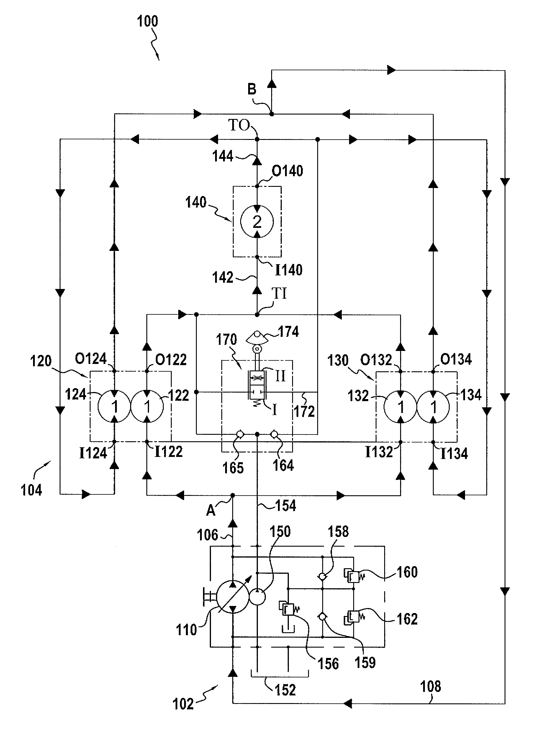
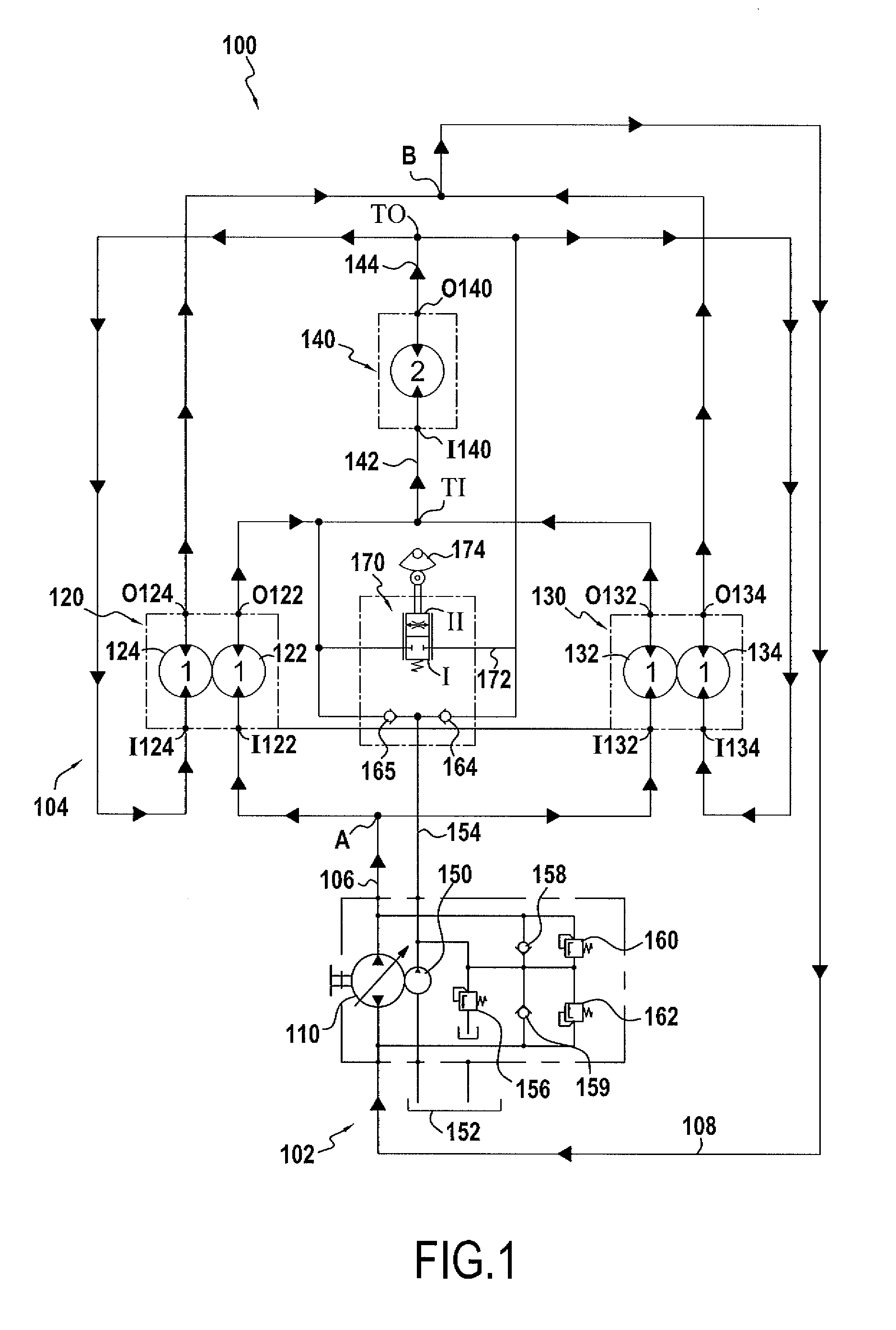
[0053]a hydraulic transmission circuit of the invention is described below with reference to FIG. 1. This hydraulic transmission circuit is mounted in a three-wheel vehicle (not shown) that it serves to propel.

[0054]This circuit 100 comprises a pump portion 102 and a drive portion 104.

[0055]The pump portion 102 comprises two main ducts, namely a common feed duct 106 and a common discharge duct 108, which ducts are connected to respective ones of the main orifices of a pump 110.

[0056]In order to feed the circuit 100 with fluid, a booster pump 150 is used that is coupled to the pump 110. Said booster pump 150 draws hydraulic fluid from a reservoir 152 and injects it into a feed duct 154. In order to limit the pressure in the feed line 154, a pressure limiter valve 156 is provided that is suitable for connecting the feed duct 154 to the reservoir 152 in the event that a predetermined pressure value is exceeded.

[0057]The feed duct 154 is connected via a first check valve 158 to the comm...


PUM


Abstract

A hydraulic circuit including: at least one primary motor comprising at least first and second distinct sub-motors, the first sub-motor having a first main orifice, and the second sub-motor having a second main orifice; and at least one secondary motor;in which circuit said first main orifice of the primary motor(s) is connected to a first main orifice of the secondary motor(s) via a first series duct, and the second main orifice of the primary motor(s) is connected to a second main orifice of the secondary motor(s) via a second series duct.This configuration of circuit makes coupling possible between the primary motor(s) and the secondary motor(s).

Description

FIELD OF THE INVENTION[0001]The invention relates to synchronizing hydraulic motors, and in particular motors connected to rotary drive members such as the wheels of a vehicle.BACKGROUND OF THE INVENTION[0002]In general, hydraulic motors are used for driving a rotary member such as a wheel, a roller of a roller compactor, a crawler track, etc. Usually, the outlet shaft drives one or more wheels of a vehicle.[0003]It is frequent for it to be necessary to synchronize the speed of rotation of the various rotary members driven by the motors. For example, in a vehicle driven by two wheels disposed on a common axle, it is necessary for said wheels to rotate at the same speed, at least most of the time.[0004]When the driven rotary members are wheels, they are not necessarily wheels that are situated at the opposite ends of the same axle of a vehicle. They may be any wheels that are to be synchronized. In particular, they may be two wheels disposed on the same side of a vehicle. The motors ...

Claims


Application Information

Patent Timeline
Patent Type & Authority Patents(United States)
IPC IPC(8): F16D31/02
CPCF16H61/448F16H61/456Y10T137/85978
Inventor HEREN, JEAN
Owner POCLAIN HYDRAULICS IND
Why Eureka
Try Eureka