
Liquid discharge head with multi-section energy application chambers

a technology of energy application chamber and liquid discharge head, which is applied in printing and other directions, can solve the problems of reducing affecting the discharge efficiency of liquid, and breaking the air bubble by the ink in the energy application chamber, so as to prevent the occurrence of cavitation and reduce the discharge efficiency

Inactive Publication Date: 2013-05-28
CANON KK
View PDF8 Cites 5 Cited by
  • Summary
  • Abstract
  • Description
  • Claims
  • Application Information

AI Technical Summary

Benefits of technology

This patent aims to provide a liquid discharge head that has a nozzle shape that can improve discharge efficiency and prevent cavitation. The invention achieves this by reducing the reduction in discharge efficiency and preventing the occurrence of cavitation.

Problems solved by technology

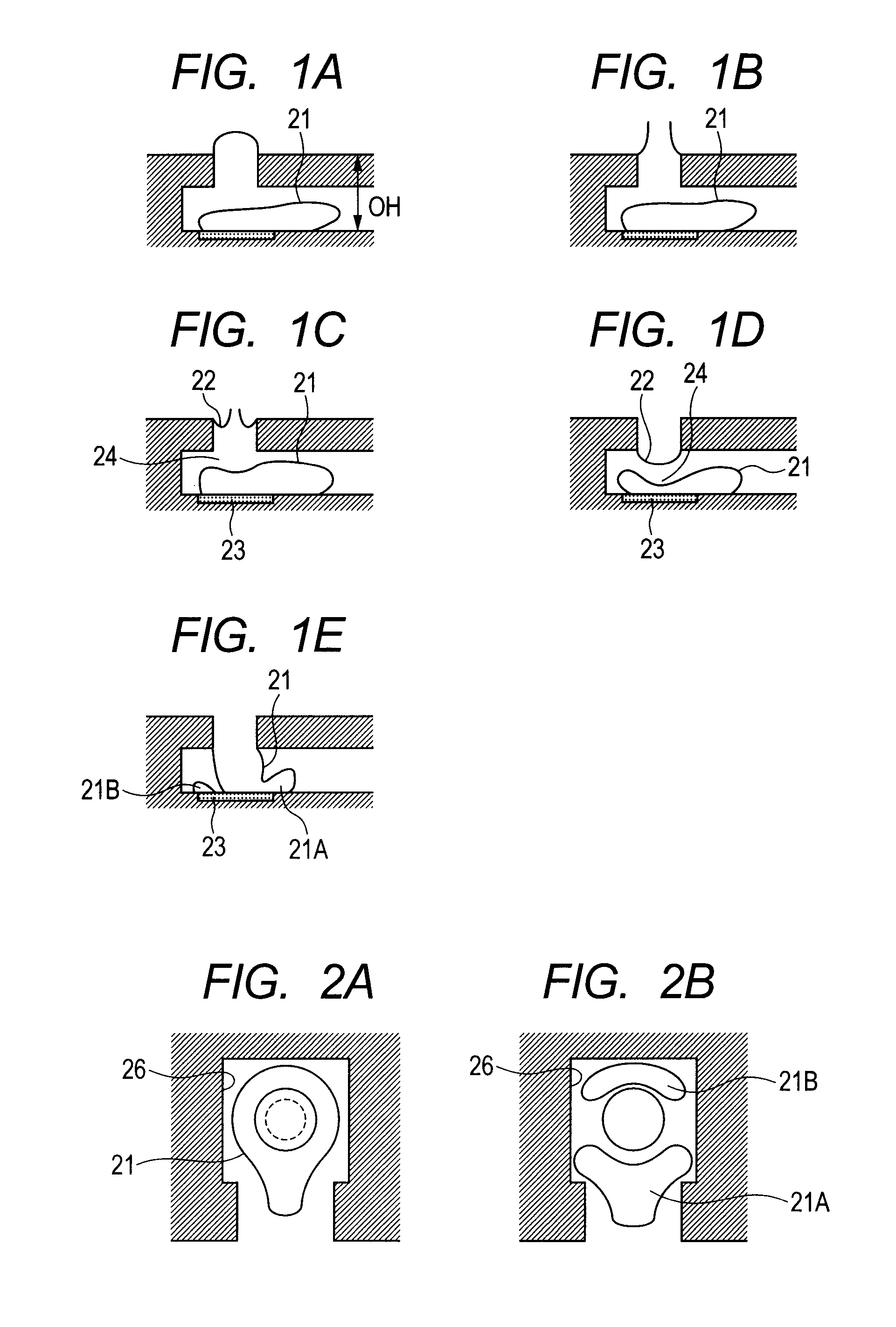
When the air bubble vanishes, the air bubble is crushed and broken by the ink in the energy application chamber.
At this time, the air bubble is broken, which may damage a member around the air bubble.
Specifically, cavitation caused by driving of the heat generating element may damage a surface of the heat generating element.
This damage may reduce recording image quality.
However, with such a liquid discharge method, occurrence of cavitation cannot be completely prevented, but cavitation may occur.
This is because the air bubble 21 having become the annular air bubble has high surface tension due to the collision with the energy application chamber wall, and cannot maintain the annular shape.
On the other hand, the air bubble 21B does not communicate with air, and thus causes cavitation in vanishing.
The cavitation reduces durability of the heat generating element.
Specifically, it has been found that ink discharge efficiency is reduced.

Method used


Image

  • Liquid discharge head with multi-section energy application chambers
  • Liquid discharge head with multi-section energy application chambers
  • Liquid discharge head with multi-section energy application chambers

Examples


first embodiment

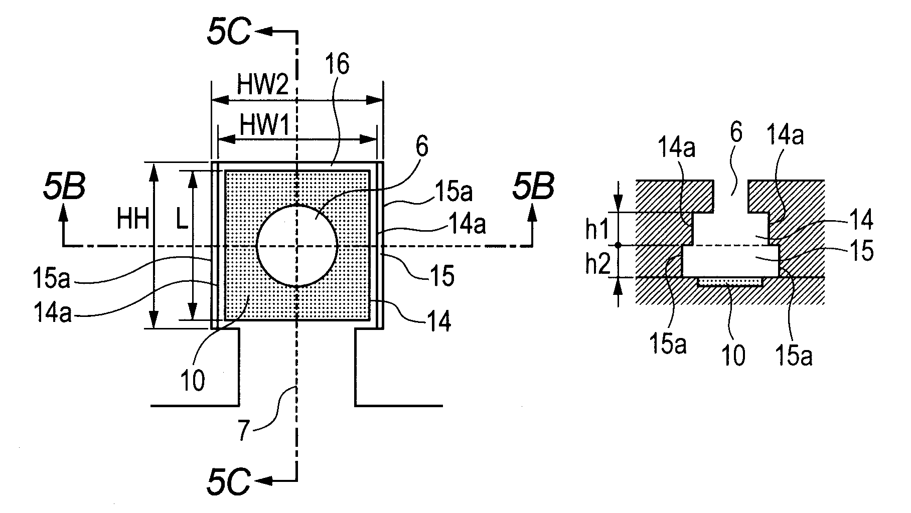
[0042]FIG. 5A is a plan view of an ink discharge portion of a recording head 1 according to a first embodiment seen in a direction perpendicular to a main surface of a substrate 4. FIG. 5B is a sectional view taken along the line 5B-5B drawn through a diameter of a circular discharge port 6 illustrated in FIG. 5A, and FIG. 5C is a sectional view taken along the line 5C-5C perpendicular to the line 5B-5B.

[0043]First, sizes of components that constitute the recording head 1 of this embodiment will be described. For a heat generating element 10, a length L in a direction from an ink supply port through an ink flow path 7 (also referred to as an ink supply direction) is 24.4 μm, and a length in a direction perpendicular to the ink supply direction is formed is 24.8 μm. A length HH in the ink supply direction that is a size of both a first energy application chamber or section 14 and a second energy application chamber or section 15 in FIG. 5A is 27 μm. A length HW1 of the first energy a...

second embodiment

[0053]A second embodiment of the present invention will be described.

[0054]FIG. 6A is a plan view of an ink discharge portion of a recording head 1 according to the second embodiment seen in a direction perpendicular to a main surface of a substrate 4. FIG. 6B is a sectional view taken along the line 6B-6B drawn through a diameter of a circular discharge port 6 illustrated in FIG. 6A, and FIG. 6C is a sectional view taken along the line 6C-6C perpendicular to the line 6B-6B.

[0055]Sizes of components that constitute the recording head 1 of this embodiment will be described.

[0056]For the heat generating element 10, a length L in a direction from an ink supply port through an ink flow path 7 to the discharge port 6 (also referred to as an ink supply direction) is 24.4 μm, and a length in a direction perpendicular to the ink supply direction is 24.8 μm. A length HH in the ink supply direction that is a size of both a first energy application chamber 14 and a second energy application ch...

third embodiment

[0063]Next, a third embodiment of the present invention will be described.

[0064]FIG. 7A is a plan view of an ink discharge portion of a recording head 1 according to the third embodiment seen in a direction perpendicular to a main surface of a substrate 4. FIG. 7A is the same as FIG. 5A. Specifically, in this embodiment, lengths (L, HH, HW1 and HW2) of portions of the discharge portion in plan view are the same as in the first embodiment. However, in this embodiment, shapes of the portions in sectional views taken along the lines 7B-7B and 7C-7C in FIG. 7A are different from those in the above-described embodiment.

[0065]In this embodiment, as illustrated in FIG. 7B, a wall 15a of a second energy application chamber 15 is not parallel but is inclined with respect to an ink discharge direction (direction perpendicular to the main surface of the substrate 4).

[0066]As described in the first embodiment, the wall 15a of the second energy application chamber 15 may prevent collision with a...


PUM


Abstract

Provided is a liquid discharge head including a discharge port; an energy application chamber that includes a heat generating element, and communicates with the discharge port; and a flow path that supplies the liquid to the energy application chamber, wherein the energy application chamber includes a first energy application chamber communicating with the discharge port, and a second energy application chamber communicating with the first energy application chamber and the flow path, a distance between facing side walls of the second energy application chamber is larger than that of the first energy application chamber in a section perpendicular to a liquid supply direction from the flow path to the energy application chamber, and for side walls of the energy application chambers formed on a back side in the liquid supply direction, the first energy application chamber and the second energy application chamber share the wall.

Description

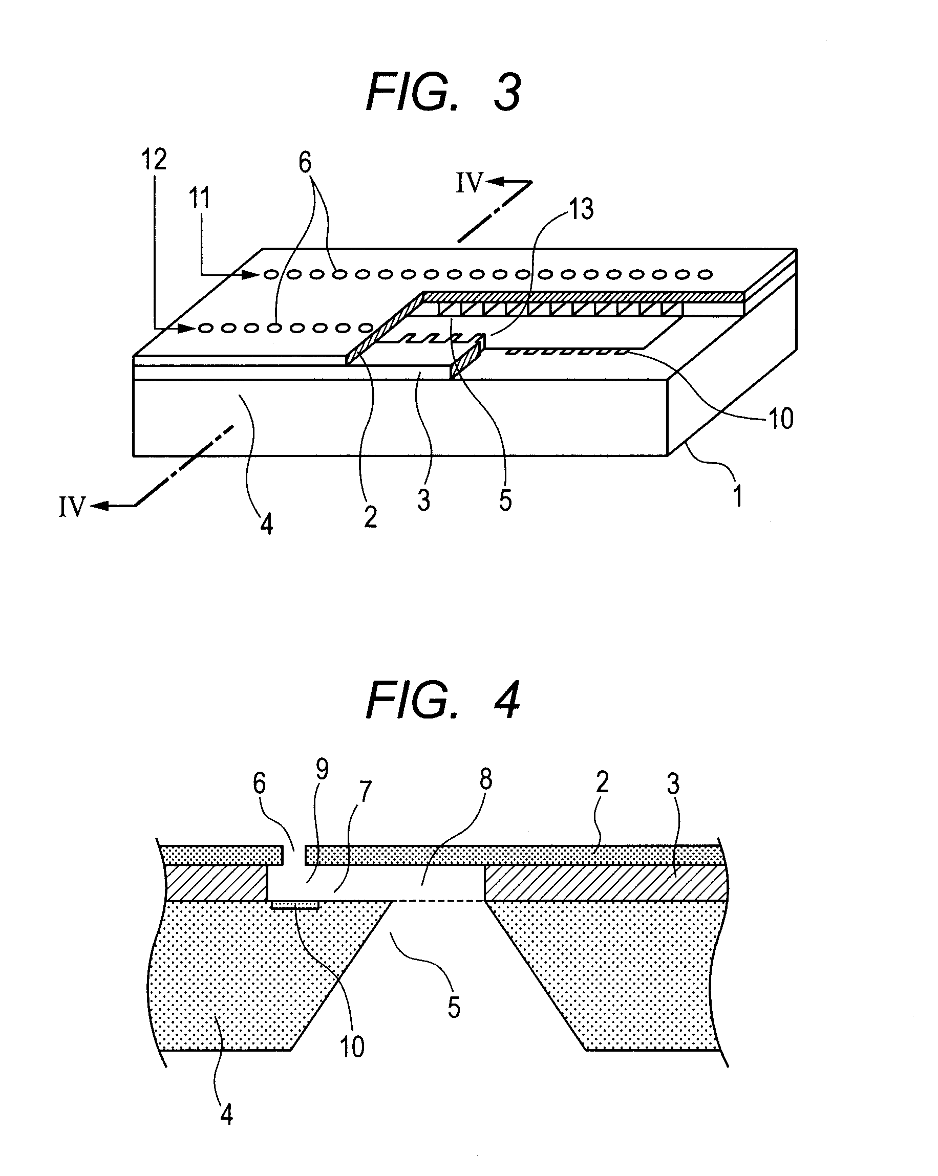
BACKGROUND OF THE INVENTION[0001]1. Field of the Invention[0002]The present invention relates to a liquid discharge head for discharging a liquid droplet of an ink liquid to record on a recording medium, and more particularly to a liquid discharge head for performing ink jet recording.[0003]2. Description of the Related Art[0004]An ink discharge method using an electricity-heat transducing element includes first providing an electric signal to a heat generating element placed in an energy application chamber to heat the heat generating element in a state where ink is supplied into the energy application chamber through an ink flow path to fill the energy application chamber. Thus, ink around the heat generating element in the energy application chamber is instantaneously heated and reaches the boiling point and boils, and an air bubble is generated on the heat generating element. A large blowing pressure of the air bubble generated at this time provides kinetic energy to the ink in ...

Claims


Application Information

Patent Timeline
Patent Type & Authority Patents(United States)
IPC IPC(8): B41J2/05
CPCB41J2/1404B41J2002/14169
Inventor NAGATSUKA, TOSHIKAZU
Owner CANON KK
Learn More