
Damping element for decoupling elements, in particular for membrane bellows

a technology of decoupling elements and damping elements, which is applied in the direction of pipe elements, rigid pipes, flexible pipes, etc., can solve the problems of material fatigue in conventional systems, and achieve the effect of enhancing the stability of the seat of damping elements

Active Publication Date: 2013-06-04
WESTFALIA METALLSCHLAUCHTECHN
View PDF26 Cites 16 Cited by
  • Summary
  • Abstract
  • Description
  • Claims
  • Application Information

AI Technical Summary

Benefits of technology

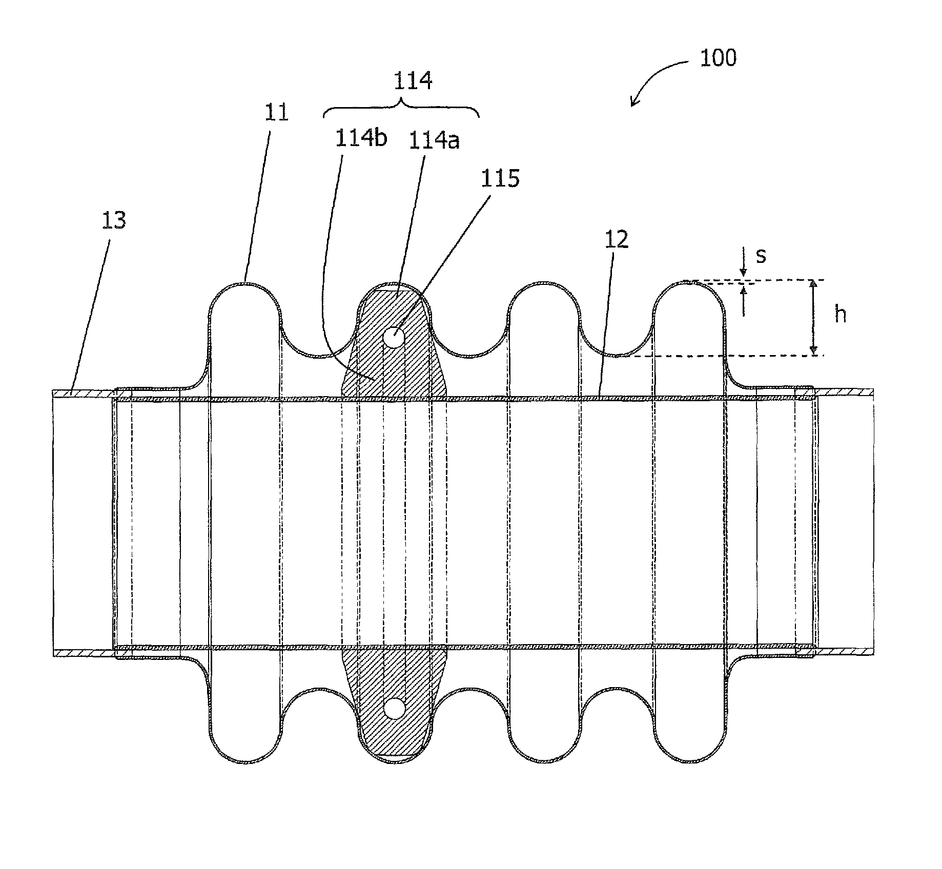
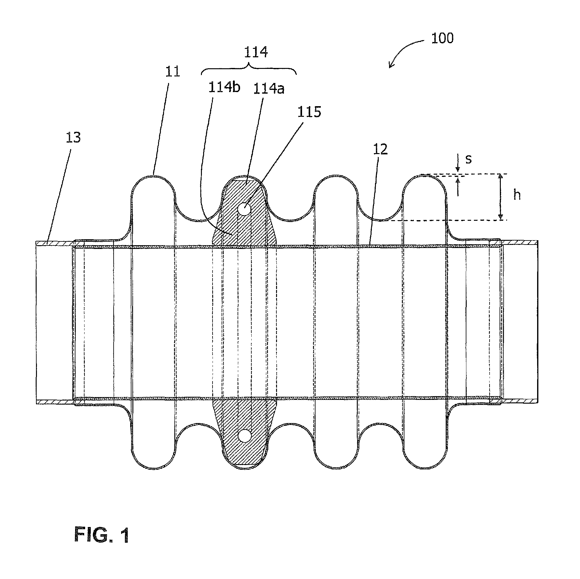
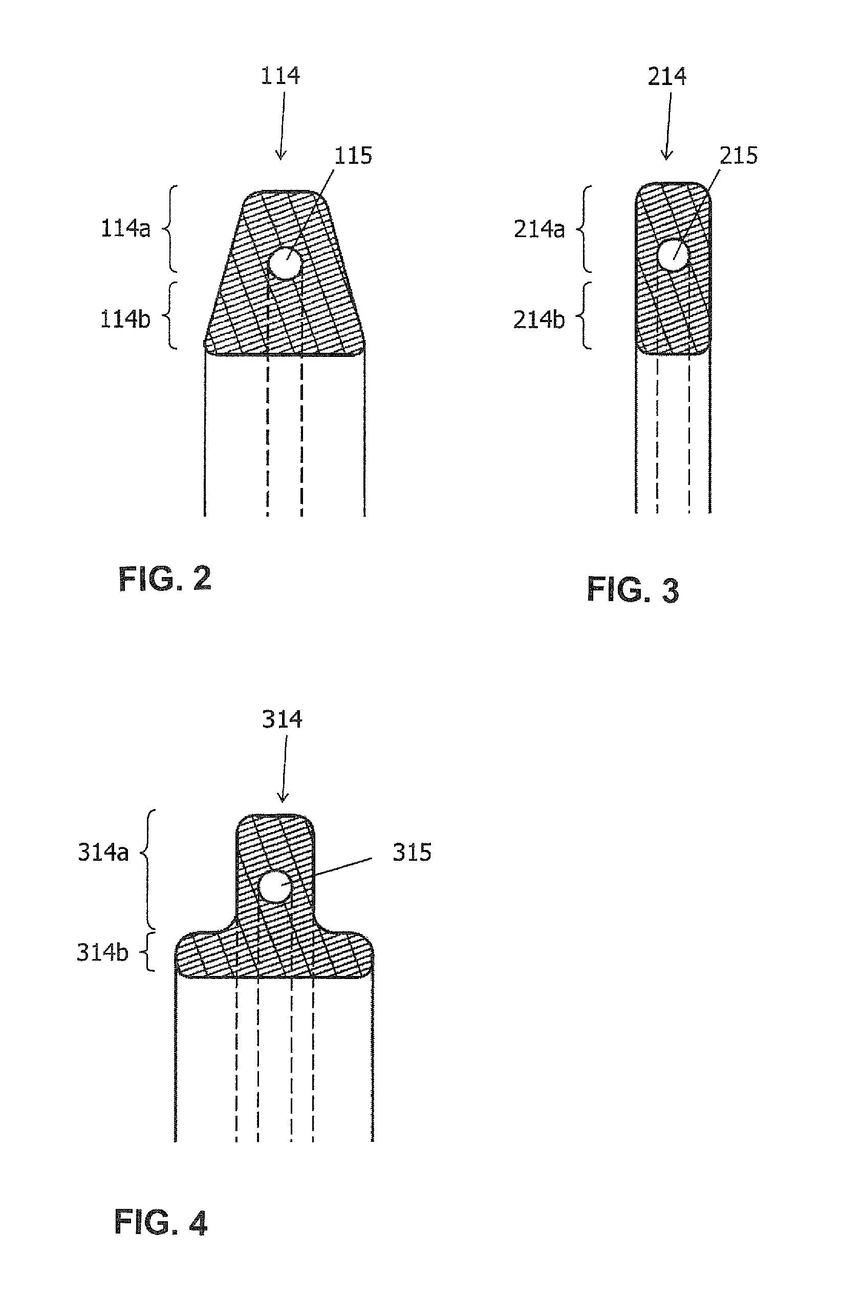
[0013]The afore-described damping element and the associated decoupling element advantageously enable or exhibit positive coupling between the woven fabric of the damping element and the exterior hose. Surprisingly, it has been observed in practical applications that such arrangement significantly extends the service life under typical (vibration) loads, while simultaneously attaining excellent damping of natural oscillations of the hose system.
[0014]For example, the exterior hose may be, in particular, a metal bellow, most preferred a membrane bellow. Metal bellows are frequently used in decoupling elements of exhaust gas conduits, because they provide a highly flexible, gas-tight connecting structure. A “membrane bellow” is here a metal bellow which is not constructed from a single-piece pipe, but is composed of individual ring elements and / or a wound band. The stiffness of metal bellows and in particular membrane bellows is typically less than 10 N / mm, i.e. very small. However, the damping element of the invention can be used successfully to sufficiently dampen natural vibrations of such metal bellows.
[0018]Moreover, the damping element may preferably have a pretension with respect to the interior hose and / or with respect to the exterior hose. This may be achieved by making the inside diameter of the damping element slightly smaller than the outside diameter of the interior hose, or by making the outside diameter of the damping element slightly greater than the inside diameter of the exterior hose. The pretension further enhances the stability of the seat of the damping elements on the exterior hose and interior hose, respectively.

Problems solved by technology

These conventional systems suffer from material fatigue.

Method used


Image

  • Damping element for decoupling elements, in particular for membrane bellows
  • Damping element for decoupling elements, in particular for membrane bellows
  • Damping element for decoupling elements, in particular for membrane bellows

Examples


Embodiment Construction

[0027]Throughout all the figures, same or corresponding elements may generally be indicated by same reference numerals. Identical reference symbols or reference symbols that differ by a multiple of 100 refer to identical or similar components in the Figures. These depicted embodiments are to be understood as illustrative of the invention and not as limiting in any way. It should also be understood that the figures are not necessarily to scale and that the embodiments are sometimes illustrated by graphic symbols, phantom lines, diagrammatic representations and fragmentary views. In certain instances, details which are not necessary for an understanding of the present invention or which render other details difficult to perceive may have been omitted.

[0028]In this context, the term “woven fabric” is defined generally a regular or irregular arrangement of filament- or fiber-shaped elements, for example metal wires. Due to its structure which includes many intermediate spaces and bends ...


PUM


Abstract

A decoupling element for a conduit includes an interior hose made of metal and a corrugated exterior hose surrounding the interior hose, with a hollow-cylindrical gap formed between the corrugated exterior hose and the interior hose. At least one damping element is arranged in the gap, with the damping element(s) constructed of a woven fabric made of a high-temperature-resistant material and having an outside surface with at least one bulge, wherein the bulge positively engages with a corrugation of the exterior hose. The exterior hose may be a membrane bellows. The woven fabric may be a metallic material. The at least one damping element covers, along the rotation axis, preferably a proportional length of at least 20% of the hollow-cylindrical gap and has preferably a static stiffness in the radial direction of less than 100 N / mm.

Description

CROSS-REFERENCES TO RELATED APPLICATIONS[0001]This application claims the priority of German Patent Application, Serial No. 10 2009 039 300.5, filed Aug. 31, 2009, pursuant to 35 U.S.C. 119(a)-(d), the content of which is incorporated herein by reference in its entirety as if fully set forth herein.BACKGROUND OF THE INVENTION[0002]The present invention relates to a damping element for arrangement in a corrugated exterior hose. The invention also relates to a decoupling element for conduits, in particular exhaust gas conduits for motor vehicles, which includes a damping element of this type.[0003]The following discussion of related art is provided to assist the reader in understanding the advantages of the invention, and is not to be construed as an admission that this related art is prior art to this invention.[0004]Decoupling elements, which are arranged, for example, in motor vehicles between the motor and the downstream sections of the exhaust gas system, frequently include a coa...

Claims


Application Information

Patent Timeline
Patent Type & Authority Patents(United States)
IPC IPC(8): F16L9/18
CPCF01N13/16F01N13/1816F16L51/026F16L55/033
Inventor WEISS, MATTHIASMUNKER, KARL-HEINZBAUMHOFF, DIETMARGERHARD, ANDREASSCHENK, KARSTENHENKELMANN, MICHAELSELTER, OLIVERHAUK, STEFAN
Owner WESTFALIA METALLSCHLAUCHTECHN
Learn More