Apparatus for supplying surgical staple line reinforcement

a technology for surgical staples and accessories, applied in the field of accessories for supplying surgical staples, can solve the problems of significantly reducing recovery time in the musculoaponeurotic area, and achieve the effect of tightening the buttress material

Inactive Publication Date: 2013-06-04
WL GORE & ASSOC INC
View PDF73 Cites 1455 Cited by
  • Summary
  • Abstract
  • Description
  • Claims
  • Application Information

AI Technical Summary

Benefits of technology

[0023]Animal-derived buttress materials (such as, for example, bovine, porcine, equine, and human products) may have difficulties associated with their placement on the working surfaces (for example the anvil and cartridge jaw surfaces) of surgical staplers. Animal-derived buttress materials cannot typically reach the consistent and thin profiles while maintaining the required strength associated with preferred synthetic buttress materials. An advantage of the present invention is that unlike traditional applications cards which do not allow successful placement of thin buttress materials, a buttress material 3 having a thickness less than 0.5 millimeters may be accurately and successfully positioned onto the working surfaces of a surgical stapler using the present apparatus.
[0024]Further, animal-derived buttress materials routinely use added steps to apply or actuate adhesives to the outer surface of their materials. For instance, some products utilize rehydration techniques, while others utilize paste-like or gel-type adhesives which need to be applied and smoothed onto the buttress material 3 prior to use. Paste-like or gel-type adhesives allow for sliding of the buttress materials on the working surfaces of a surgical stapler during loading. The present invention does not require added application or actuation steps when a ready to use adhesive such as a pressure sensitive adhesive is employed. A pressure sensitive adhesive can be ready to use by simple removal of a release liner.
[0025]An unexpected advantage of the present apparatus is that thinner buttress materials such as synthetic non-animal derived materials and other materials particularly those less than 0.5 millimeters in thickness are more readily applied to a stapler working surfaces than is possible with traditional applicator means. The buttress material 3 is able to be readily adhered or placed back to the crotch of a surgical stapler and successfully cover the staple lines with the present apparatus, because the body can be made thin enough to reach to the crotch of a stapler. This ease of placement also allows the buttress material 3 to be attached onto the working surfaces of a stapler without bunching.
[0026]Examples of suitable synthetic buttress materials include but are not limited to: bioabsorbable or biodegradable materials or webs, non-bioabsorbable materials or webs, expanded polytetrafluoroethylene (“ePTFE”) such as disclosed in U.S. Pat. No. 5,810,855, synthetic materials, or other suitable buttress materials. One advantage of using synthetic buttress materials is that there is no need to rehydrate synthetic materials prior to use, and they will have a more consistent thickness. The surgical buttress material 3 may further comprise an adhesive on at least the outermost surface relative to the body of the apparatus. The adhesive may be a ready to use adhesive such as a pressure sensitive adhesive or further may be an activatable adhesive which may be moistened or otherwise activated prior to use. A release liner, such as PET release films, or other coated webs or sheets may be applied over an adhesive to protect it until it is ready for use. The release liner may be utilized to cover the buttress material 3 and pre-applied adhesive so that the liner may readily separate from the adhesive on the surgical buttress material 3, thus maintaining the integrity of the adhesive, and allowing it to be easily prepared for use. One advantage of the present apparatus is that the adhesive may be pre-applied and essentially be uniformly distributed over the buttress material. Thus, eliminating the need for any smoothing or spreading as required by unevenly distributed gel or paste-like adhesives traditionally used on buttress materials (see

Problems solved by technology

Inhibiting or preventing tearing at the stapled incision site in musculoaponeurotic areas also significantly decreases recovery time.

Method used


Image

  • Apparatus for supplying surgical staple line reinforcement
  • Apparatus for supplying surgical staple line reinforcement
  • Apparatus for supplying surgical staple line reinforcement

Examples


example 1

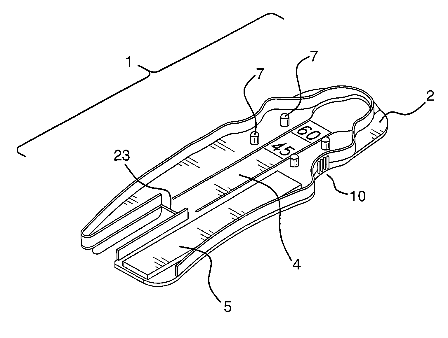
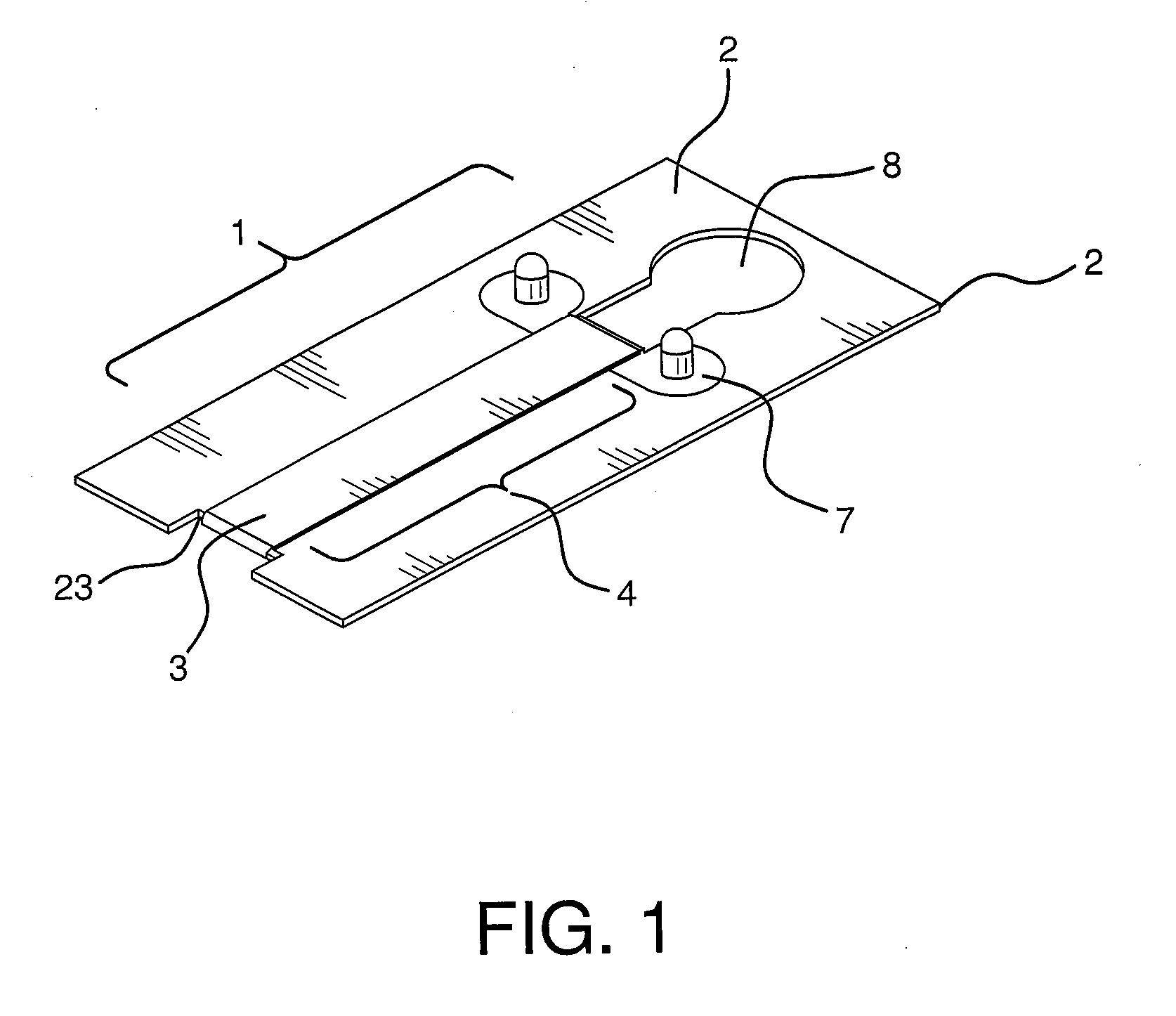
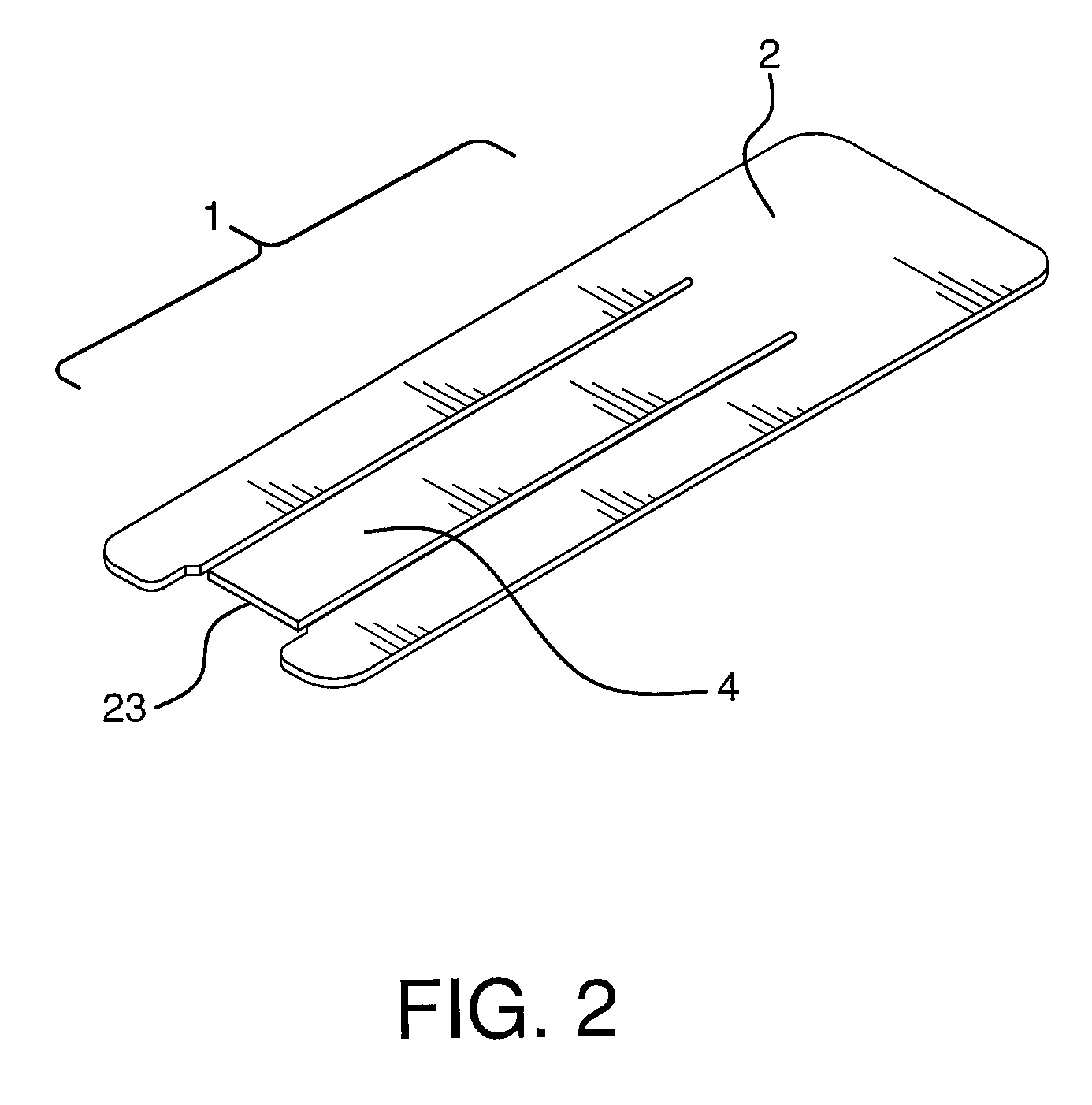
[0035]A 30 mil (0.076 cm) thick card forming the body of the apparatus (dimension 10 cm L×5.7 cm W) was made by injection molding polycarbonate and configured to aid in applying surgical staple line buttress (SLR) material to the jaws of a commercially available stapler. The SLR receiving area, stapler restraining area and the pivot of the SLR card were created through a three-sided cutout (S1×S2×S3) of the polycarbonate card using a razor tool. The lengths of the longitudinal cuts (S1& S3) on the card are about ˜50% of the polycarbonate card (approximately 4.7 cm) and starting approximately 0.6 cm from one end of the card. The length of the latitudinal cut (S2) is sized to accommodate the width of the SLR and jaws of a commercially available stapler (approximately 1 cm).

[0036]The receiving area is defined by the three sides of the S1, S2 and S3 cuts. The uncut side of the receiving area defines the pivot. The end of the card closest to the pivot is the stapler restraining area. The...

example 2

[0037]One piece of SLR material with one side having a pressure sensitive adhesive (PSA) with a release liner for covering the PSA is placed on the receiving area of the polycarbonate card prepared as in Example 1.

[0038]The SLR material is precut with connected perforated tabs that extend beyond the width of the receiving area.

[0039]The SLR material is adapted to fit onto the receiving area and can be attached to the polycarbonate card on each side with perforated tabs that extend past the width of the receiving area. The perforated tabs of the SLR are attached to the polycarbonate card using a second PSA on the opposite side of the first PSA liner.

example 3

[0040]For a ready-to-use SLR card, the SLR is attached to the polycarbonate card prior to packaging.


PUM

PropertyMeasurementUnit
thickaaaaaaaaaa
thicknessaaaaaaaaaa
thickaaaaaaaaaa

Abstract

An apparatus for supplying surgical buttress material to a surgical stapler is provided. The apparatus has a pivotable area for attaching surgical buttress material. The apparatus may also have an adhesive and a release liner disposed over the buttress material.

Description

CROSS REFERENCE TO RELATED APPLICATION[0001]This application claims priority to U.S. Provisional Application No. 60 / 978,178, filed Oct. 8, 2007.FIELD OF THE INVENTION[0002]The present invention relates to an apparatus for supply of surgical staple line reinforcement material to a surgical stapler.BACKGROUND OF THE INVENTION[0003]Surgical stapling devices are employed by surgeons to sequentially or simultaneously apply one or more rows of surgical fasteners such as staples or two-part fasteners to body tissue for the purpose of joining segments of body tissue together. Such stapling devices generally consist of a pair of jaws (one being the cartridge side and one being the anvil side) or arm-like structures between which body tissue to be joined is placed. When the instrument is actuated, or “fired,” longitudinally moving firing bars contact staple drive members in one of the jaws, thereby pushing surgical staples through body tissue and into an anvil in the opposite jaw which crimps...

Claims


Application Information

Patent Timeline
Patent Type & Authority Patents(United States)
IPC IPC(8): A61B17/03
CPCA61B17/072A61B17/07292B33Y80/00
Inventor ESKAROS, SHERIFDIPIETRO, JR., JOSEPH J.RUSSELL, MARY JOWINTERLING, MICHAEL
Owner WL GORE & ASSOC INC
Why Eureka
Try Eureka