Liquid accommodating container, tank unit, and liquid ejecting system

Active Publication Date: 2013-06-04
SEIKO EPSON CORP
View PDF35 Cites 17 Cited by
  • Summary
  • Abstract
  • Description
  • Claims
  • Application Information

AI Technical Summary

Benefits of technology

[0010]An advantage of some aspects of the invention is that it provides a technique by which in a liquid accommodating container in which a liquid injection port and a flow path opened to the air are separately provided, even in a case where the state of the liquid accommodating container has changed, a possibility that liquid may flow out from the flow path opened to the air toward the outside can be reduced.
[0017]According to the liquid accommodating container stated in Application 3, in the use position, since the liquid outlet is located closer to the outermost surface of the liquid accommodating chamber, the remaining amount of liquid in the liquid accommodating chamber can be reduced. Further, in the injection position, since the liquid outlet is located closer to the outermost surface of the liquid accommodating chamber, even in a case where the liquid accommodating container has been made to be in the injection position in a state where the remaining amount of liquid in the liquid accommodating chamber has become small, a state where a liquid surface in the liquid accommodating chamber is at a higher position than the liquid outlet can be more reliably maintained. That is, in the injection position, a state where the liquid outlet contacts with liquid in the liquid accommodating chamber without intervention of air can be more reliably maintained. Accordingly, a possibility that air may flow to the liquid ejecting apparatus side through the liquid outlet at the time of liquid injection can be reduced.Application 4
[0019]According to the liquid accommodating container stated in Application 4, the liquid accommodating chamber, the air accommodating chamber, and the second flow path can be easily formed by the container main body of a concave shape and the film which blocks the opening of the container main body. Further, the airtightness of the inside of the liquid accommodating container can be easily secured.Application 5
[0021]According to the liquid accommodating container stated in Application 5, the airtightness of the inside of the liquid accommodating container can be easily secured by the film and liquid leakage due to breakage of the film can also be prevented.Application 6
[0025]According to the tank unit stated in Application 7, it is possible to easily form two liquid accommodating containers. Further, since it is possible to form substantially two liquid accommodating containers by single molding, it is possible to improve the production efficiency of the liquid accommodating container.Application 8
[0029]According to the liquid ejecting system stated in Application 9, a liquid ejecting system can be provided which supplies ink to the printer by using the liquid accommodating container in which a possibility that ink may flow out from the flow path opened to the air toward the outside is reduced.

Problems solved by technology

Such problems are not limited to the ink tank and are problems common to a liquid accommodating container which is for accommodating therein liquid that a liquid ejecting apparatus ejects and in which a liquid injection port and a flow path opened to the air are separately provided.

Method used


Image

  • Liquid accommodating container, tank unit, and liquid ejecting system
  • Liquid accommodating container, tank unit, and liquid ejecting system
  • Liquid accommodating container, tank unit, and liquid ejecting system

Examples


first example

A. FIRST EXAMPLE

A-1. Configuration of Liquid Ejecting System

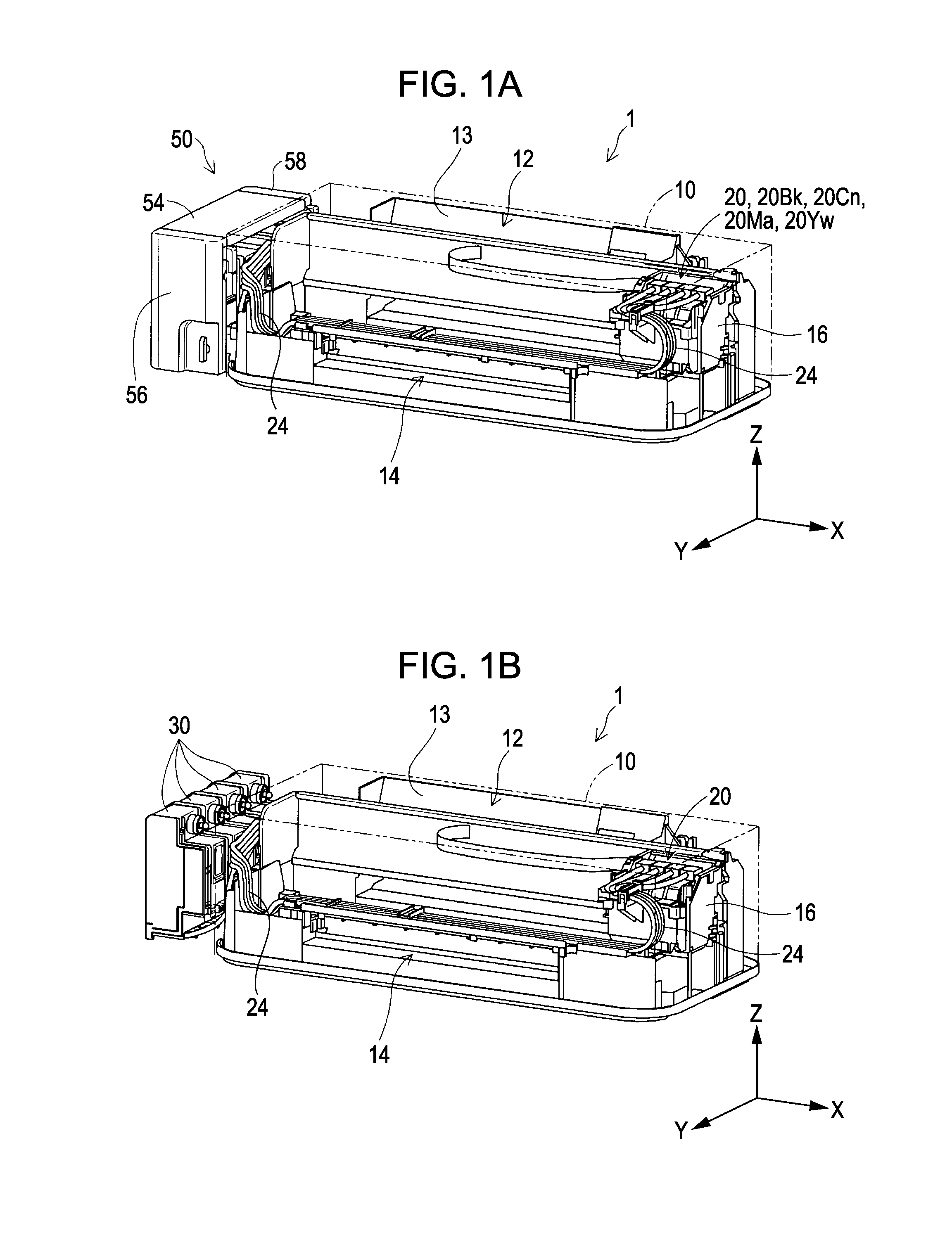
[0055]FIGS. 1A and 1B are diagrams for describing a liquid ejecting system 1 of the first example. FIG. 1A is an exterior perspective view of the liquid ejecting system 1. FIG. 1B is an exterior perspective view of the liquid ejecting system 1 and is a diagram illustrating liquid accommodating containers 30 of the first example of the invention. In addition, in FIGS. 1A and 1B, X, Y, and Z axes being right angles to each other are shown in order to specify a direction. In addition, also with respect to the subsequent drawings, the X, Y, and Z axes are shown as necessary.

[0056]As shown in FIG. 1A, the liquid ejecting system 1 includes an ink jet printer 12 (also simply referred to as a “printer 12”) as a liquid ejecting apparatus, and a tank unit 50. The printer 12 includes a paper feed section 13, a paper discharge section 14, a carriage 16 and four sub-tanks 20. The four sub-tanks 20 contain ink of different colors. Specif...

second example

B. SECOND EXAMPLE

[0127]FIG. 18 is an exploded perspective view of an ink tank 30a of the second example. FIG. 19 is a perspective view of a tank main body 32a of the second example. This example is different from the first example in that one ink tank 30a is provided with two flow paths opened to the air 300 and two liquid accommodating chambers 340 (FIG. 4). In addition, with respect to the same configuration as that in the first example, the same reference numeral is applied and explanation is omitted. Further, a positional relationship between the liquid injection port 304, the air-side opening 351, the liquid-side opening 352, and the port opened to the air 318, which the ink tank 30a of the second example includes, is the same as the positional relationship (FIGS. 9A to 11B, 13A, and 13B) in the first example.

[0128]As shown in FIG. 18, the ink tank 30a includes the tank main body 32a, two films 34, two sheet members 316, the film 322, two plug members 302, and cover members 42 ...

first modified example

C-1. First Modified Example

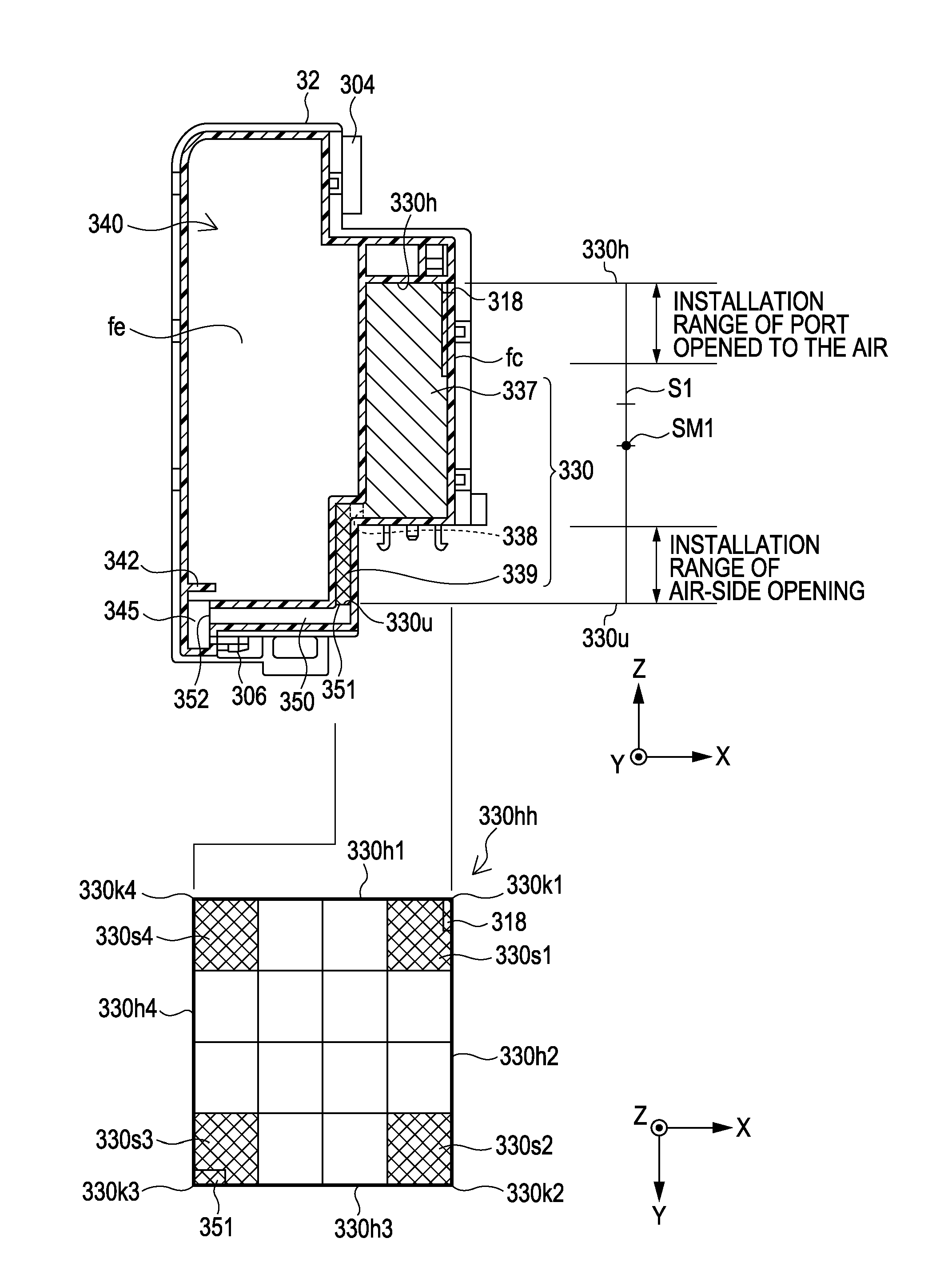
[0133]In the above examples, the air accommodating chamber 330 is provided with the upper accommodating chamber 337 of a rectangular parallelepiped shape, the lower accommodating chamber 339 of a rectangular parallelepiped shape having volume different from that of the upper accommodating chamber 337, and the communication flow path 338 making the upper and lower accommodating chambers communicate with each other. However, the shape of the air accommodating chamber 330 is not limited to thereto. That is, it is acceptable if it is a configuration having the given volume capable of retaining ink flowed back from the liquid accommodating chamber 340. For example, the air accommodating chamber 330 may also be configured only by one chamber of a rectangular parallelepiped shape or may also have a configuration having three or more of accommodating chambers.


PUM


Abstract

A liquid accommodating container in which in a use position, a port opened to the air is provided at a position that is closer to an air chamber uppermost surface and is included in a first corner portion, an air-side opening is provided at a position that is closer to an air chamber lowermost surface and is included in a second corner portion which is at a diagonal position to the first corner portion, and a liquid-side opening is provided at a position satisfying the following conditions (a) and (b), (a) a position closer to a liquid chamber lowermost surface with respect to the vertical direction in the use position and (b) a position which is included in the second corner portion that is at a position equivalent to a diagonal position to the first corner portion.

Description

[0001]This application claims priority to Japanese Patent Application No. 2010-160364, filed Jul. 15, 2010, the entirety of which is incorporated by reference herein.BACKGROUND[0002]1. Technical Field[0003]The present invention relates to a liquid accommodating container, a tank unit provided with a plurality of liquid accommodating containers, and a liquid ejecting system provided with the liquid accommodating containers.[0004]2. Related Art[0005]A printer that is one example of a liquid ejecting apparatus performs printing by discharging ink from a recording head onto a recording target (for example, printing paper). As the technique of supplying ink to a recording head, a technique of supplying ink from an ink cartridge disposed on a recording head to the recording head and also supplying ink from an ink tank disposed outside a liquid ejecting apparatus to the ink cartridge or the head through a tube is known (for example, JP-A-2005-219483, JP-A-2005-1284, and JP-A-2005-199693). ...

Claims


Application Information

Patent Timeline
Patent Type & Authority Patents(United States)
IPC IPC(8): B41J2/175
CPCB41J2/175B41J2/17509B41J2/17513B41J2/17523B41J2/17553
Inventor ISHIZAWA, TAKUSHIMIZU, YOSHIAKITAKEDA, YUKI
Owner SEIKO EPSON CORP
Why Eureka
Try Eureka