Safety switch using heat shrinkage tube and secondary battery including the same

a safety switch and heat shrinkage tube technology, applied in the field of safety switches, can solve the problems of shrinkage tube shrinkage to operate the safety switch of the battery, and achieve the effects of reducing internal energy accumulated in the battery cell, effectively discharging heat generated, and consuming charge energy of the battery cell

Active Publication Date: 2013-06-04
LG ENERGY SOLUTION LTD
View PDF14 Cites 1 Cited by
  • Summary
  • Abstract
  • Description
  • Claims
  • Application Information

AI Technical Summary

Benefits of technology

[0012]As a result of a variety of extensive and intensive studies and experiments to solve the problems as described above, the inventors of the present invention have developed a safety switch that uses a heat shrinkage tube as an operating device, and found that, when the temperature of a battery exceeds a predetermined temperature level, the heat shrinkage tube shrinks to reliably interrupt external charge current or forcibly consume energy accumulated in a battery cell, thereby greatly improving the safety of the battery. The present invention has been completed based on these findings.
[0014]Specifically, when a battery or a battery pack is exposed to an abnormal environment, with the result that the temperature of the battery or the battery pack exceeds a predetermined temperature level due to the temperature outside the battery or the battery pack or heat generated in the battery or the battery pack, the heat shrinkage tube shrinks to operate the switch of the battery. As a result, external charge current is interrupted or internal energy accumulated in the battery cell is consumed through current interruption or current conduction, whereby the safety of the battery is secured. Consequently, the safety switch can operate rapidly and sensitively with a high reliability when the battery is abnormally operated. Also, the safety switch is not constructed in the form of a circuit, and therefore, the safety switch can operate even when a circuit of the battery is abnormal, and it is not necessary to modify a circuit related to the operation of the battery.
[0020]In accordance with another aspect of the present invention, there is provided a secondary battery having the safety switch with the above-stated construction, as a member for securing the safety of the battery when the battery is overheated (“safety member”), mounted at the outside of a battery cell.
[0029]The resistor may emit heat, during the current conduction at the electric wire connection part, to consume charge energy of the battery cell, thereby reducing internal energy accumulated in the battery cell. In this case, a large amount of internal electric energy accumulated in the battery cell is consumed through the current conduction. Consequently, a great quantity of heat may be generated from the resistor due to the resistance of the resistor. For this reason, it is necessary to effectively dissipate heat generated by the current conducted during the forced discharge, and therefore, it is preferable that the resistor be located at a region outside the battery cell where the influence due to the heat emission is minimized.
[0030]According to circumstances, the resistance value of the resistor may be controlled to control the degree of the forced discharge. The resistance value of the resistor may be decided within a predetermined range which is greater than the sum of the resistance of wires used to connect the resistor and the resistance of the safety switch but is not excessively high. When the resistance value is too small, severe heat may be generated, with the result that the battery may explode due to instantaneous discharge. When the resistance value is too large, on the other hand, the discharge speed is reduced, with the result that the safety of the battery is not improved.

Problems solved by technology

Specifically, when a battery or a battery pack is exposed to an abnormal environment, with the result that the temperature of the battery or the battery pack exceeds a predetermined temperature level due to the temperature outside the battery or the battery pack or heat generated in the battery or the battery pack, the heat shrinkage tube shrinks to operate the switch of the battery.

Method used


Image

  • Safety switch using heat shrinkage tube and secondary battery including the same
  • Safety switch using heat shrinkage tube and secondary battery including the same
  • Safety switch using heat shrinkage tube and secondary battery including the same

Examples


Embodiment Construction

[0041]Now, preferred embodiments of the present invention will be described in detail with reference to the accompanying drawings. It should be noted, however, that the scope of the present invention is not limited by the illustrated embodiments.

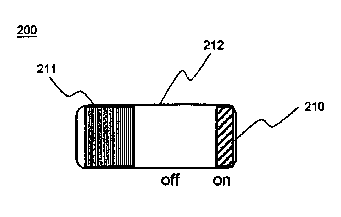
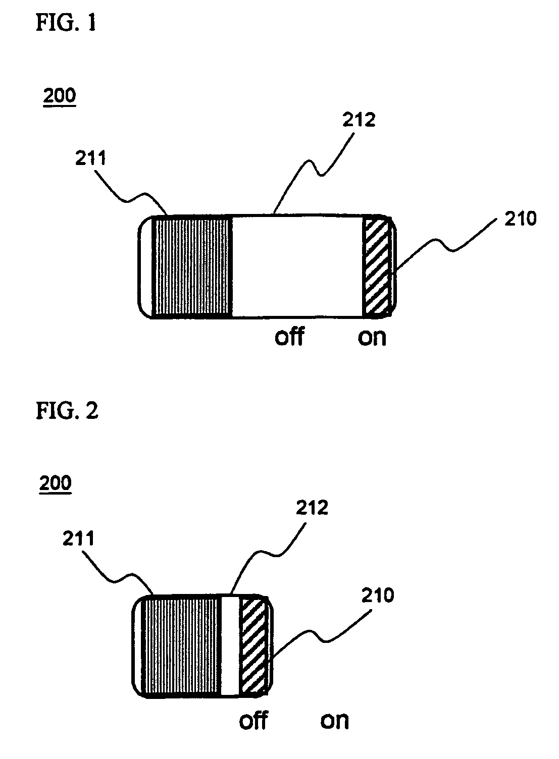
[0042]FIGS. 1 and 2 are typical views illustrating the operating principle of a safety switch according to a preferred embodiment of the present invention. Specifically, FIG. 1 illustrates the state of the safety switch, during the normal operation of the battery, before the operation of the safety switch is performed, and FIG. 2 illustrates the state of the safety switch, when the battery is abnormally operated, after the operation of the safety switch is performed. For convenience of description, the safety switch shown in FIGS. 1 and 2 will be hereinafter referred to as a charge switch.

[0043]Referring to FIGS. 1 and 2, the safety switch 200 is constructed in a structure in which one side of a heat shrinkage tube 212 is fixed by a support ...


PUM

PropertyMeasurementUnit
temperatureaaaaaaaaaa

Abstract

Disclosed herein is a safety switch including a tube that is capable of shrinking when exposed to temperatures in excess of a predetermined temperature level (“heat shrinkage tube”), wherein the length of the heat shrinkage tube is changeable to control current conduction, one end of the heat shrinkage tube is fixed, and the other end of the heat shrinkage tube is connected to an electric wire connection part, such that current conduction or current interruption is accomplished by the change in length of the heat shrinkage tube when the heat shrinkage tube is varied due to heat. When a battery or a battery pack is exposed to an abnormal environment, with the result that the temperature of the battery or the battery pack exceeds a predetermined temperature level, the heat shrinkage tube of the safety switch shrinks to directly interrupt external charge current, thereby preventing the further charge of the battery or the battery pack. Furthermore, internal energy accumulated in the battery cell is forcibly consumed, thereby fundamentally preventing the progress of the abnormal operation of the battery or the battery pack. Consequently, the safety of the battery is secured.

Description

CROSS REFERENCE TO RELATED APPLICATIONS[0001]The present application is a national phase entry under 35 U.S.C. §371 of International Application No. PCT / KR2007 / 003410, filed Jul. 14, 2007, published in English, which claims the benefit of Korean Patent Application No. KR10-2006-0066647, filed Jul. 18, 2006. The disclosures of said applications are incorporated by reference herein.FIELD OF THE INVENTION[0002]The present invention relates to a safety switch including a tube that is capable of shrinking when exposed to temperatures in excess of a predetermined temperature level (“heat shrinkage tube”), and, more particularly, to a safety switch constructed in a structure in which the length of the heat shrinkage tube is changeable to control current conduction, one end of the heat shrinkage tube is fixed, and the other. end of the heat shrinkage tube is connected to an electric wire connection part, such that current conduction or current interruption is accomplished by the change in l...

Claims


Application Information

Patent Timeline
Patent Type & Authority Patents(United States)
IPC IPC(8): H01M10/50H01H37/74H01M50/583
CPCH01H37/48H01M10/4235H01M2/348H01M2/34Y02E60/10H01M50/581H01M50/583H01M50/20
Inventor RYU, JI HEONCHOI, JEONG HEESHIN, YOUNGJOON
Owner LG ENERGY SOLUTION LTD
Why Eureka
Try Eureka