Secondary battery and method for producing the same

a secondary battery and a technology for secondary batteries, applied in the field of secondary batteries, can solve the problems of low porosity of the void volume in the porous film, insufficient charge/discharge characteristics and high-rate charge/discharge characteristics under low temperature environments of the secondary battery, etc., to improve the safety of the battery, improve the large-current discharge characteristics, and high porosity

Active Publication Date: 2008-07-22
PANASONIC CORP
View PDF33 Cites 28 Cited by
  • Summary
  • Abstract
  • Description
  • Claims
  • Application Information

AI Technical Summary

Benefits of technology

[0009]In view of the foregoing, it is an object of the present invention to improve the large-current discharge characteristics, especially at a low temperature for a secondary battery in which a porous film for improving the safety of the battery is provided on its electrode plate.
[0024]With the present invention, it is possible to improve the large-current discharge characteristics, especially at a low temperature for a secondary battery in which a porous film for improving the safety of the battery is bonded to its electrode plate. Moreover, with the present invention, it is possible to produce such a secondary battery at low cost.

Problems solved by technology

When a porous film is formed using a slurry in which spherical or substantially spherical primary particles that are separated from each other are dispersed, and an electrode plate that has been integrated with the porous film is used, a short circuit failure or the like is difficult to occur during formation of an electrode plate group.
As a result, the ratio of the void volume in the porous film (the porosity) becomes low, and the high-rate charge / discharge characteristics and the charge / discharge characteristics under low temperature environments of the secondary battery therefore tend to be insufficient.
A secondary battery including a porous film in which primary particles are filled at high density may not be able to provide sufficient characteristics, for example, as the power source of a mobile phone, a notebook computer or the like.
In particular, when used under a temperature environment of 0° C. or lower, the secondary battery may suffer a significant deterioration in charge / discharge characteristics, posing a practical problem.

Method used


Image

  • Secondary battery and method for producing the same
  • Secondary battery and method for producing the same
  • Secondary battery and method for producing the same

Examples


example 1

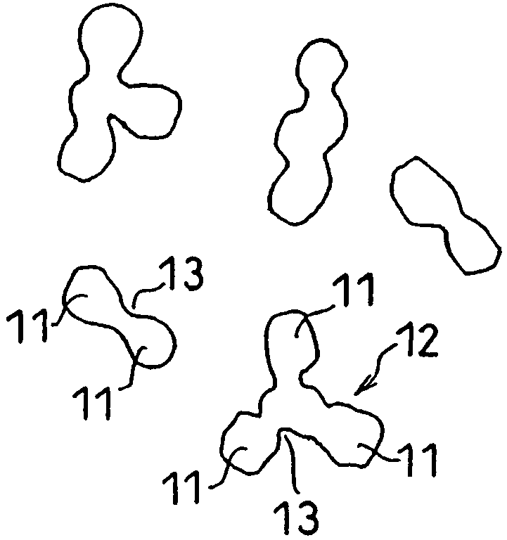
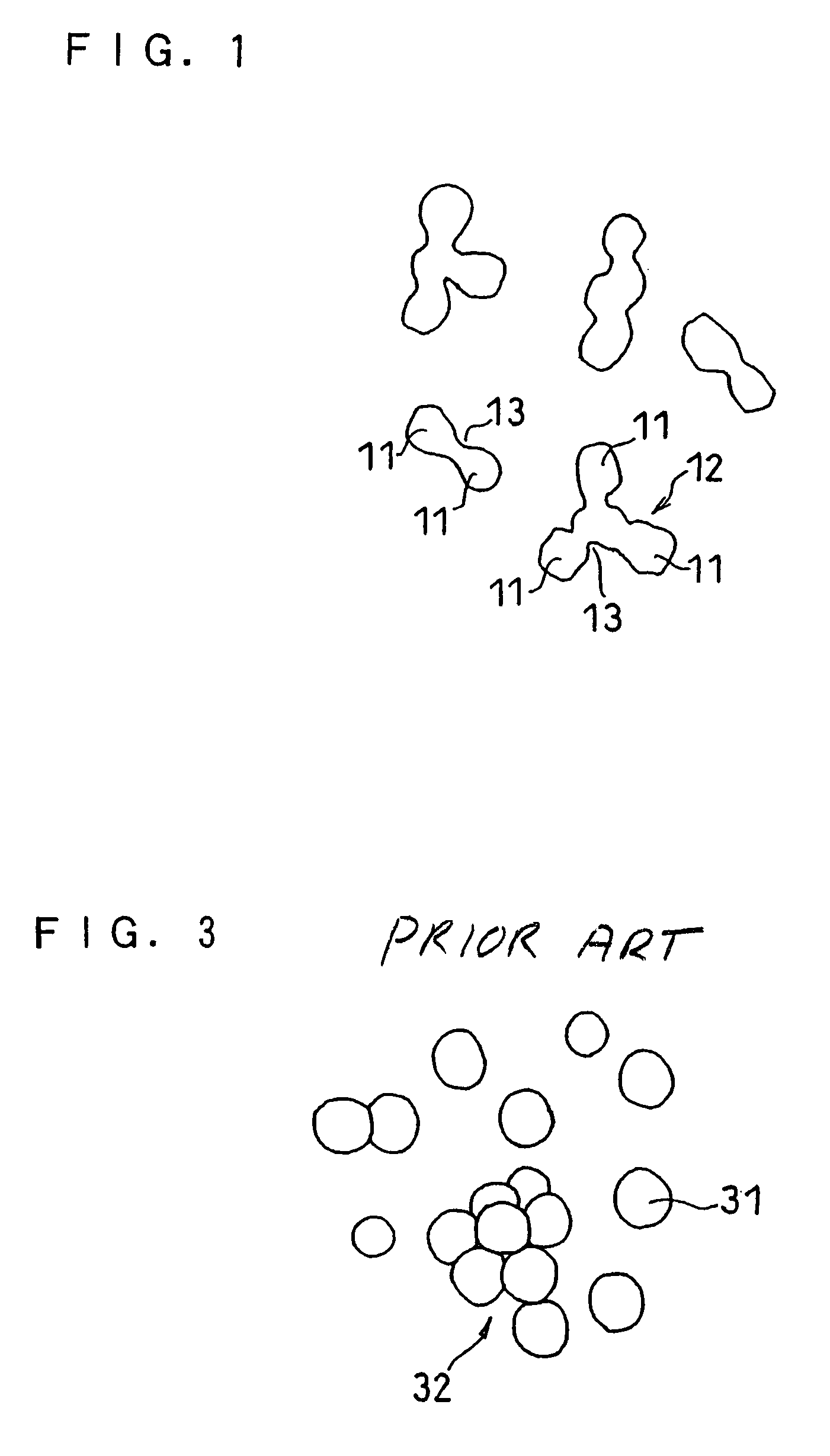
(I) Preparation of Ceramic Particles Including Polycrystalline Particles

[0076]Here, ceramic particles including α-alumina were prepared.

[0077]First, aluminum tributoxide, which is aluminum alkoxide, was provided. Pure water was added to aluminum tributoxide, and the whole was subjected to hydrolysis to form an alumina gel, which was then dried. The thus obtained dry gel was used as the ceramic precursor.

[0078]Subsequently, the dry gel serving as the ceramic precursor was fired at 1200° C. for three hours, thus obtaining a fired material comprising α-alumina. As a result of determining the average particle size of the single crystal cores of α-alumina from SEM pictures for the obtained fired material, it was about 0.2 μm.

[0079]The obtained fired material was crushed with a jet mill. Here, the particles having the respective bulk densities and BET specific surface areas shown in Table 1 were obtained by controlling the crushing conditions such that the bulk density of the ceramic part...

example 2

[0108]Here, ceramic particles including α-alumina were also prepared.

[0109]First, ammonium dawsonite, which is aluminum ammonium salt, was provided as the alumina precursor. This was fired at 1200° C. for three hours, thus obtaining a fired material comprising α-alumina. As a result of determining the average particle size of the single crystal cores of α-alumina from SEM pictures for the obtained fired material, it was about 0.1 μm.

[0110]The obtained fired material was crushed with a jet mill. Here, the particles having the respective bulk densities and BET specific surface areas shown in Table 2 were obtained by controlling the crushing conditions such that the bulk density of the ceramic particles was 0.05 to 1.2 g / cm3 and the BET specific surface area was 3.5 to 25 m2 / g. The bulk density was also measured here by a static method using a “powder tester (product name)” manufactured by Hosokawa Micron Corporation. Observation of the obtained particles with SEM pictures confirmed th...

example 3

[0124]A lithium ion secondary battery was fabricated without using a sheet-like separator.

[0125]Here, the separator comprising a 15 μm thick microporous sheet made of a polyethylene resin was not used, and instead a porous film was formed in a large thickness on the negative electrode using the slurry A3 of Example 1. The thickness of the porous film after drying was 20 μm.

[0126]The obtained test battery exhibited a discharge capacity of 1830 mAh during discharging at a low temperature and 2 C rate, as with the battery fabricated using the slurry A3 in Example 1. Although a conventionally used sheet-like separator is expensive, it did not need to be used in the present example, so that the battery could be produced at low cost.


PUM

PropertyMeasurementUnit
temperatureaaaaaaaaaa
bulk densityaaaaaaaaaa

Abstract

In a secondary battery including a positive electrode, a negative electrode and a porous film bonded to the surface of at least one of the positive electrode and the negative electrode, the porous film includes ceramic particles and a binder, and the ceramic particles include polycrystalline particles obtained by mechanically crushing a fired material comprising a ceramic that is directly synthesized from a ceramic precursor. The porous film has a porosity of 40 to 80%, for example. The porous film can be formed by a method including the steps of: obtaining a fired material comprising a ceramic from a ceramic precursor; obtaining ceramic particles by mechanically crushing the fired material of the ceramic; obtaining a slurry including the ceramic particles and a binder; and applying the slurry onto the surface of an electrode, followed by drying.

Description

RELATED APPLICATION[0001]This application is a divisional of application Ser. No. 11 / 314,008, filed Dec. 22, 2005, which is a continuation-in-part of International Application No. PCT / JP2005 / 004120, filed on Mar. 9, 2005, which in turn claims the benefit of Japanese Application No. 2004-183949, filed on Jun. 22, 2004; which are all incorporated herein by reference.FIELD OF THE INVENTION[0002]The present invention relates to a secondary battery having excellent discharge characteristics, and more particularly to a secondary battery in which a porous film for improving the safety of the battery is provided on its electrode plate.BACKGROUND OF THE INVENTION[0003]Secondary batteries such as a lithium ion secondary battery are generally provided with an electrode plate group comprising a positive electrode, a negative electrode and a separator interposed therebetween. The separator serves to provide electrical insulation between the two electrodes and also to retain an electrolyte. Recen...

Claims


Application Information

Patent Timeline
Patent Type & Authority Patents(United States)
IPC IPC(8): H01M2/16H01M10/04C04B41/87H01M4/131H01M4/133H01M4/24H01M4/48H01M10/052H01M10/0525H01M10/24H01M10/36H01M50/443H01M50/491
CPCH01M2/164H01M4/04H01M4/131H01M4/133H01M4/24H01M4/48H01M10/052H01M10/0525H01M4/02Y10T29/49115H01M10/04H01M10/24H01M2004/021Y02E60/122Y02E60/124Y02E60/10Y02P70/50H01M10/058H01M50/491H01M50/443H01M4/13C04B41/87
Inventor IKUTA, SHIGEOFUKUMOTO, YUSUKE
Owner PANASONIC CORP
Why Eureka
Try Eureka