

Stabilized electrochemical cell active material
- Summary
- Abstract
- Description
- Claims
- Application Information
AI Technical Summary
Benefits of technology
Problems solved by technology
Method used
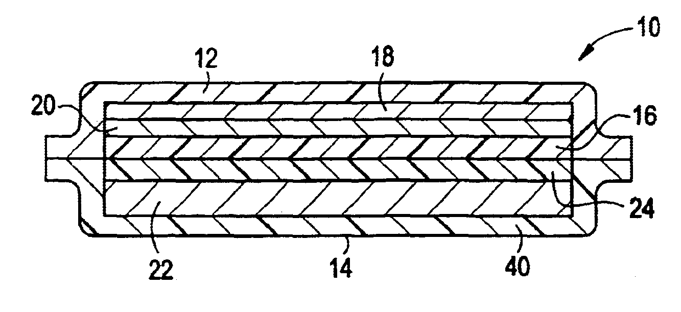
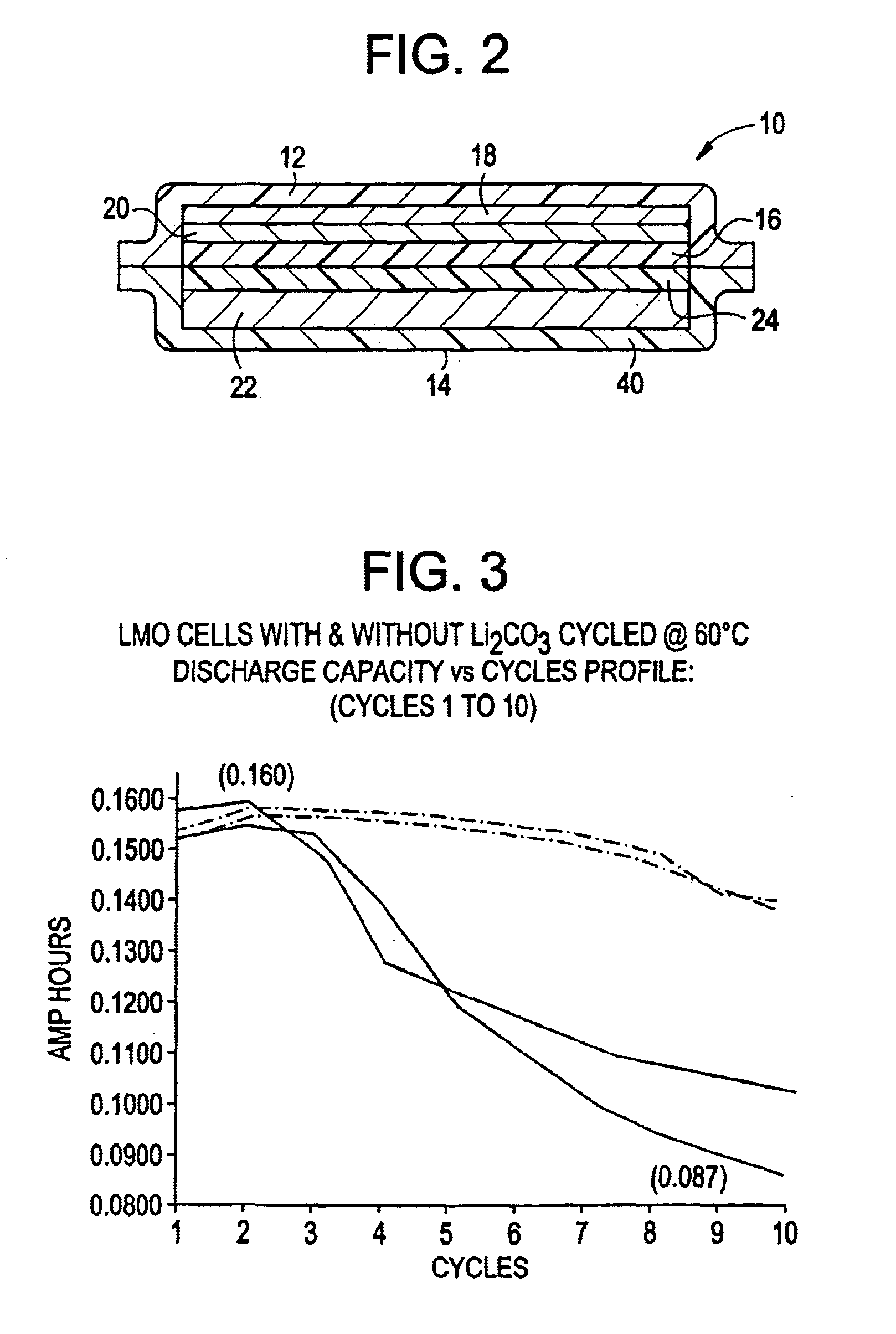
Image

Examples
example i
The anode was fabricated by solvent casting a slurry of graphite, binder, plasticizer, and solvent. The graphite used for the slurry may be either SFG-15 (Lonza G&T, Ltd; Sins, Switzerland) or BG-35 (Superior Graphite, Chicago, Ill.), Kynar Flex 2801J (a 88:12 copolymer of polyvinylidene difluoride (PVDF) and hexafloropropylene (HFP) was used as the binder, a plasticizer and an electronic grade solvent were also used. The slurry was cast onto glass and a free standing electrode was formed as the solvent was evaporated. The anode slurry composition was as follows:
ComponentWet Weight %Dry Weight %Graphite24.358.3Binder6.816.4Plasticizer10.525.3Solvent58.4—Total100.0100.0
The cathode was fabricated by solvent casting a slurry of LMO, additive (Li2CO3), conductive carbon, binder, plasticizer, and solvent. The conductive carbon used was Super P (MMM Carbon), Kynar Flex 2801J was used as the binder along with a plasticizer, and electronic grade acetone was used as the solvent. The slurry w...
example ii
Treated LMO
Non-limiting examples of the synthesis of the treated LMO of the invention are given below. The examples are illustrative of the alkali metal compounds, mixing methods, and heating steps that lead to useful treated active materials. Substitutions of starting materials, and variations of conditions may be made according to the description above.
example iia
Prepartion of Surface Modified LMO Using 1-2 Weight % Lithium Carbonate
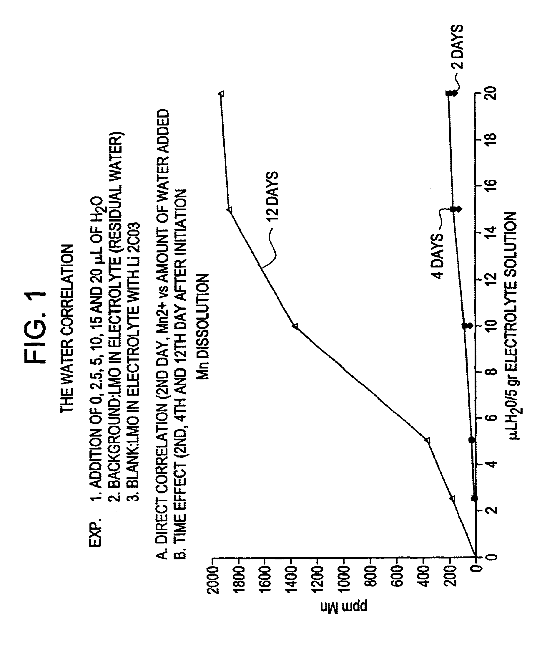
Lithium manganese oxide spinel (LMO) was obtained from Japan Energy Corporation having the specifications as per Table III, and designated Japan Energy Corporation ISR 140B. The procedure begins with mixing LMO and lithium carbonate by ball milling for 60 minutes. A low level (1-2 weight percent) of high purity lithium carbonate around 5 micron particle size is used. Such lithium carbonate is available from Pacific Lithium, New Zealand. Large ceramic media was used for this operation. This caused no attrition of the material. The media was then removed from the mixture. The mixed Li2CO3 / LMO was heated in a Box Furnace, set at between 600-750° C., for 30 minutes. The treated material was removed from the furnace and immediately transferred to a second Box Furnace set at 450° C. for 1 hour. This furnace had a good supply of flowing air throughout to minimize oxygen deficiency and to overcome the tendency of LMO to ...
PUM
| Property | Measurement | Unit |
|---|---|---|
| Temperature | aaaaa | aaaaa |
| Temperature | aaaaa | aaaaa |
| Fraction | aaaaa | aaaaa |
Abstract
Description
Claims
Application Information