

Concentrated photovoltaic and thermal solar energy collector
a solar energy collector and photovoltaic technology, applied in thermal-pv hybrid energy generation, instruments, lighting and heating apparatus, etc., can solve the problems of low energy conversion efficiency of conventional solar collectors, low heat quality, and high cost of conventional flat panel solar collectors
- Summary
- Abstract
- Description
- Claims
- Application Information
AI Technical Summary
Benefits of technology
Problems solved by technology
Method used
Image

Examples
Embodiment Construction
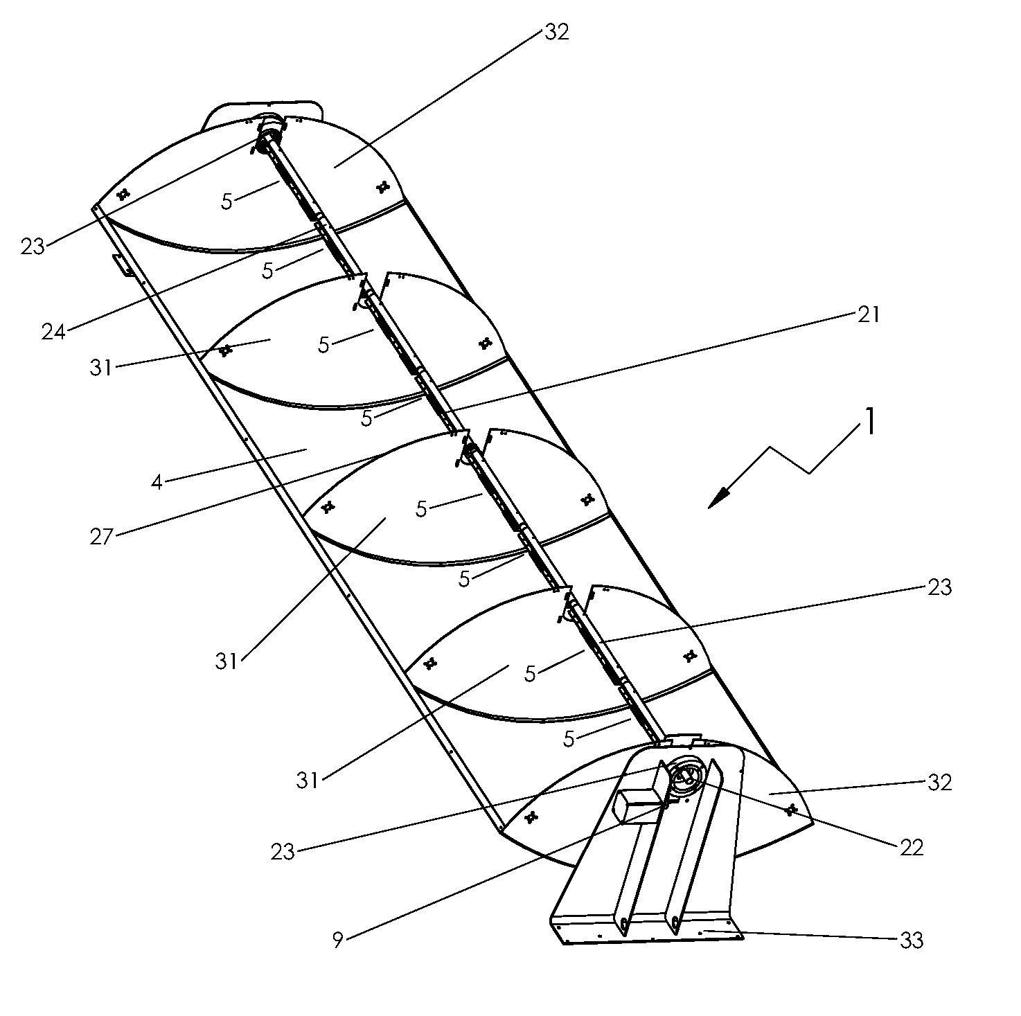
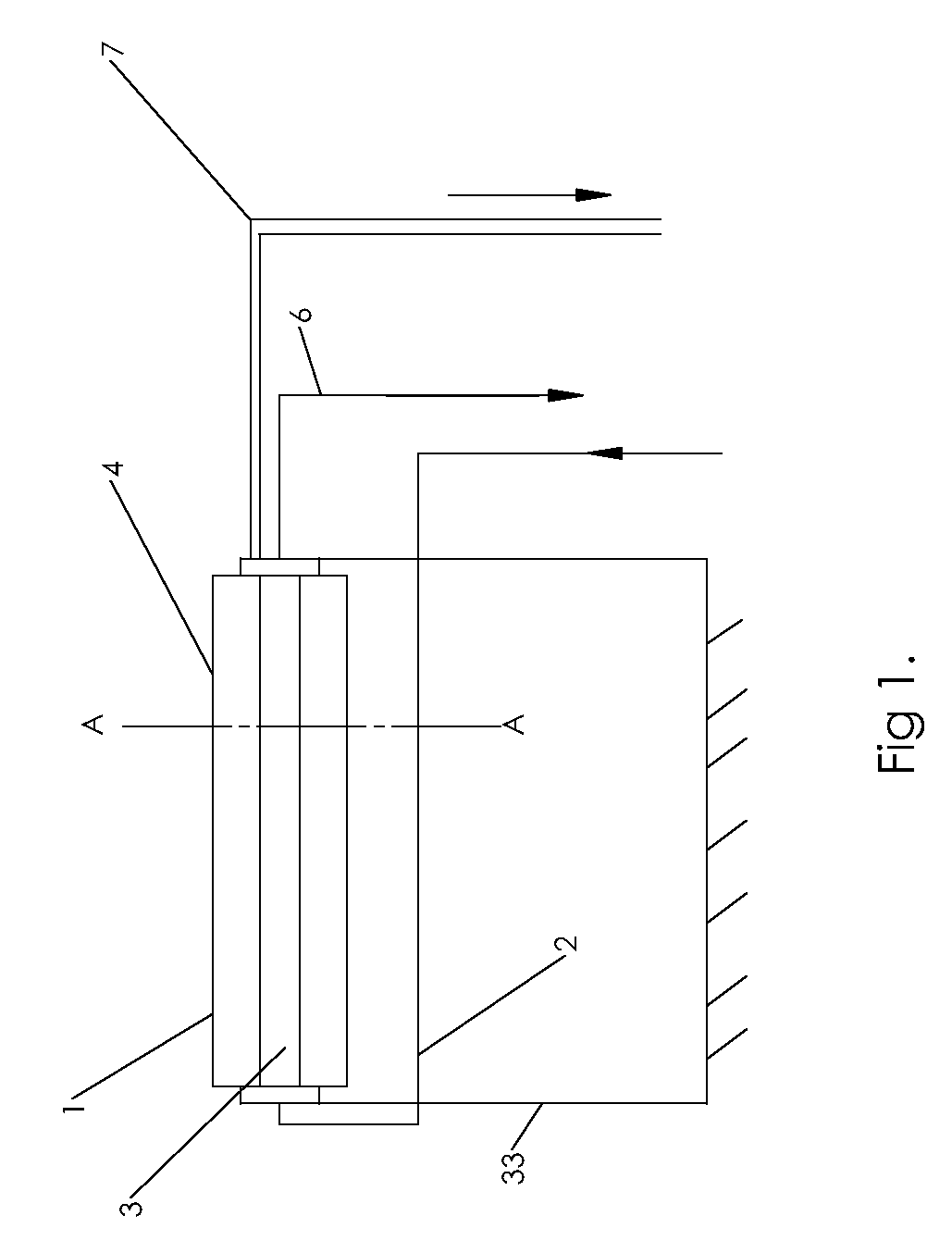
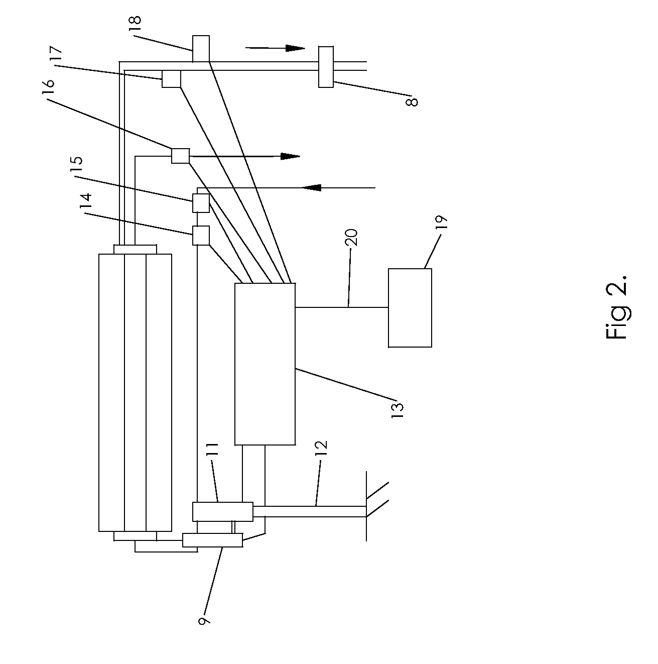
[0008]In one preferred embodiment, the solar concentrator described herein converts incident solar energy into both heat and electricity. Summing both thermal and electrical energy outputs, the conversion efficiency of an embodiment of the present invention is approximately 80%. Furthermore, a preferred embodiment of the present invention uses only one-twentieth the area of silicon cells to produce the same amount of electrical energy as a conventional solar panel, greatly reducing the material cost. This is accomplished by concentrating approximately twenty square feet of incident energy onto an approximately one square foot photovoltaic cell using a parabolic trough reflector and combining the reflector's photovoltaic target and thermal target into one device. In addition, according to a preferred embodiment, by combining the reflector's photovoltaic target and thermal target into one device and integrating structural elements of the PV and thermal solar energy collector, the user...
PUM
| Property | Measurement | Unit |
|---|---|---|
| temperatures | aaaaa | aaaaa |
| melt temperature | aaaaa | aaaaa |
| temperature | aaaaa | aaaaa |
Abstract
Description
Claims
Application Information