Laminated body, method of manufacturing substrate, substrate, and semiconductor device

a technology of laminated body and manufacturing method, which is applied in the direction of lithographic masks, etching metal masks, synthetic resin layered products, etc., can solve the problem that the generation of smears cannot be suppressed completely, and achieve the effect of improving the laser workability of the buildup layer, thin thickness and reducing the generation of smears

Inactive Publication Date: 2013-06-04
SUMITOMO BAKELITE CO LTD
View PDF14 Cites 3 Cited by
  • Summary
  • Abstract
  • Description
  • Claims
  • Application Information

AI Technical Summary

Benefits of technology

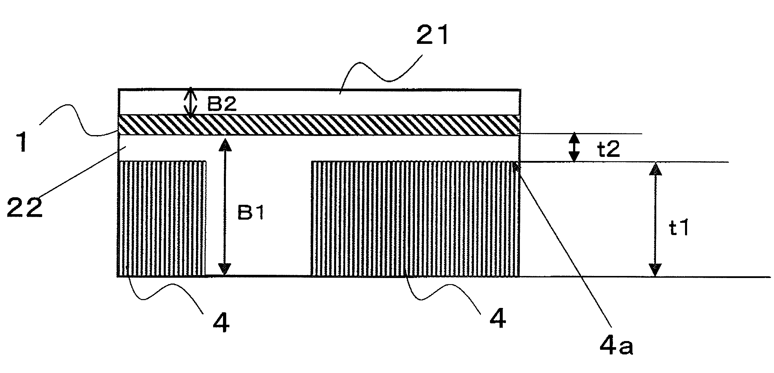
[0007]In order to improve such a problem, the present inventors have developed a buildup layer in which a glass fiber base member having very thin thickness is used. This makes it possible to improve the laser workability of the buildup layer to a certain degree. However, even if the glass fiber base member having thin thickness is used, the generation of the smear cannot be suppressed completely. It is therefore an object of the present invention to improve laser workability of a resin layer (buildup layer), in which a fiber base member having a thickness of 25 μm or less is used, by sufficiently suppressing generation of smear during subjecting the resin layer to a laser processing.

Problems solved by technology

However, even if the glass fiber base member having thin thickness is used, the generation of the smear cannot be suppressed completely.

Method used


Image

  • Laminated body, method of manufacturing substrate, substrate, and semiconductor device
  • Laminated body, method of manufacturing substrate, substrate, and semiconductor device
  • Laminated body, method of manufacturing substrate, substrate, and semiconductor device

Examples


example 1

(1) Preparation of Resin Varnish

[0152]Novolak type cyanate resin having a weight average molecular weight of about 700 (“Primaset PT-30” produced by LONZA Japan): an amount thereof with respect to a total weight of a resin composition was 23.98 wt %; biphenyl dimethylene type epoxy resin having an epoxy equivalent of 275 and a weight average molecular weight of about 2,000 (“NC-3000” produced by Nippon Kayaku Co., Ltd.): an amount thereof with respect to the total weight of the resin composition was 17.98 wt %; phenoxy resin being a copolymer of biphenyl epoxy resin and bisphenol S epoxy resin, having an epoxy group at each end and having a weight average molecular weight of 30,000 (“YX-8100H30” produced by Japan Epoxy Resins Co., Ltd.): an amount thereof with respect to the total weight of the resin composition was 5.99 wt %; phenoxy resin being a copolymer of bisphenol A and bisphenol F and having a weight average molecular weight of 60,000 (“jER4275” produced by Japan Epoxy Resin...

example 2

[0166]This Example 2 was carried out in the same manner as in the Example 1 except that a fiber base member having a thickness of 20 μm was used.

example 3

[0167]This Example 3 was carried out in the same manner as in the Example 1 except that an organic non-woven cloth having a thickness of 15 μm (“product number MBBK6C” produced by KUPARAY CO., LTD.) was used as the constituent material of the core portion.


PUM

PropertyMeasurementUnit
thicknessaaaaaaaaaa
thicknessaaaaaaaaaa
thicknessaaaaaaaaaa

Abstract

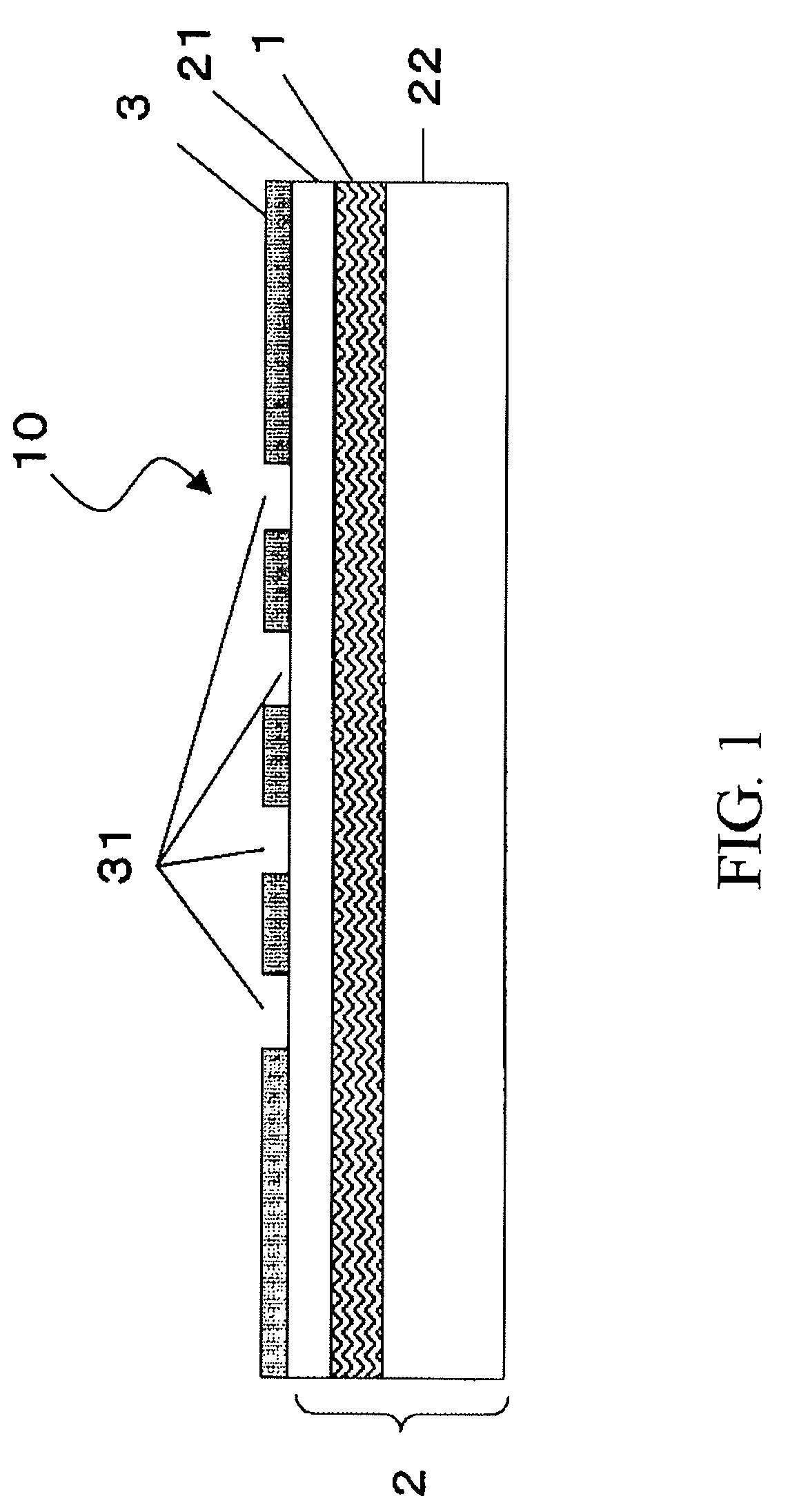
A laminated body of the present invention includes a resin layer in which a core portion composed of a fiber base member having a thickness of 25 μm or less is embedded, the resin layer having two surfaces, and the resin layer through which at least one via-hole is adapted to be formed, and a metal layer bonded to at least one of the two surfaces of the resin layer, and the metal layer having at least one opening portion provided so as to correspond to the via-hole to be formed. Further, a method of manufacturing a substrate of the present invention includes preparing the above laminated body, forming the via-hole so as to pass through the resin layer by irradiating a laser beam onto the resin layer, and removing the metal layer from the resin layer after the via-hole is formed. Further, a substrate of the present invention is manufactured by using the above method. Furthermore, a semiconductor device of the present invention includes the above substrate, and a semiconductor element mounted on the substrate.

Description

FIELD OF THE INVENTION[0001]The present invention relates to a laminated body, a method of manufacturing a substrate, a substrate, and a semiconductor device.BACKGROUND[0002]Electronic devices are becoming increasingly smaller and faster, as a result of which high-density packaging and high-density wiring of a multilayer printed wiring board are promoted. This requires that wirings provided in the multilayer printed wiring board are thinly formed and through-holes provided therein are minutely formed. In order to satisfy these requirements, a buildup-type multilayer printed wiring board is used.[0003]A rigid double-sided substrate or multilayer substrate in which a fiber base member is utilized is widely used as an internal layer which serves as a core of the multilayer printed wiring board. Further, insulating resin layers to be laminated on such a substrate are provided using a method of repeatedly coating a resin material onto the substrate, a method of laminating resin films ont...

Claims


Application Information

Patent Timeline
Patent Type & Authority Patents(United States)
IPC IPC(8): H05K1/09
CPCB32B15/14H01L23/49822H05K3/4644H05K3/4655H05K3/4673H01L21/4857Y10T428/24331H01L2224/16H01L2924/01012H01L2924/01057H01L2924/01078H05K1/0366H05K3/0035H05K3/4652H05K2201/0191H05K2203/0554H05K2203/1152B32B5/022B32B7/06B32B15/08B32B15/20B32B27/12B32B27/16B32B27/20B32B27/281B32B27/283B32B27/286B32B27/36B32B27/38B32B27/40B32B27/42B32B3/14B32B2262/02B32B2262/0261B32B2262/101B32B2264/10B32B2307/306B32B2307/718B32B2307/734B32B2307/748B32B2457/00H01L2924/00014H01L2924/00011Y10T428/249951H01L2224/0401H05K3/46H05K1/03
Inventor MORIMOTO, JUNPEIKANEDA, KENICHI
Owner SUMITOMO BAKELITE CO LTD
Why Eureka
Try Eureka