System for detecting catheterization devices

a technology of automatic identification and image data, applied in image analysis, image enhancement, instruments, etc., can solve the problems of false detection of marker spheres, unable to reliably detect balloon marker spheres, and the quality of images provided by known systems for identifying the stent location is typically limited

Inactive Publication Date: 2013-06-04
SIEMENS HEALTHCARE GMBH
View PDF8 Cites 36 Cited by
  • Summary
  • Abstract
  • Description
  • Claims
  • Application Information

AI Technical Summary

Problems solved by technology

Displaying stent struts is a challenge when a patient is large and / or steep imaging angles are involved.
Quality of images identifying stent location provided by known systems is typically limited because of reduced CNR (Contrast to Noise Ratio), for example.
Known systems also lack reliability in detection of balloon marker spheres which are X-ray radio-opaque spheres located at a distal and proximal end of a stent deployment balloon, for example.
Further, high contrast objects (like clips, guide wire tips, leads, sternal wires, as illustrated in FIG. 1) may lead to false detection of marker spheres.

Method used


Image

  • System for detecting catheterization devices
  • System for detecting catheterization devices
  • System for detecting catheterization devices

Examples


Embodiment Construction

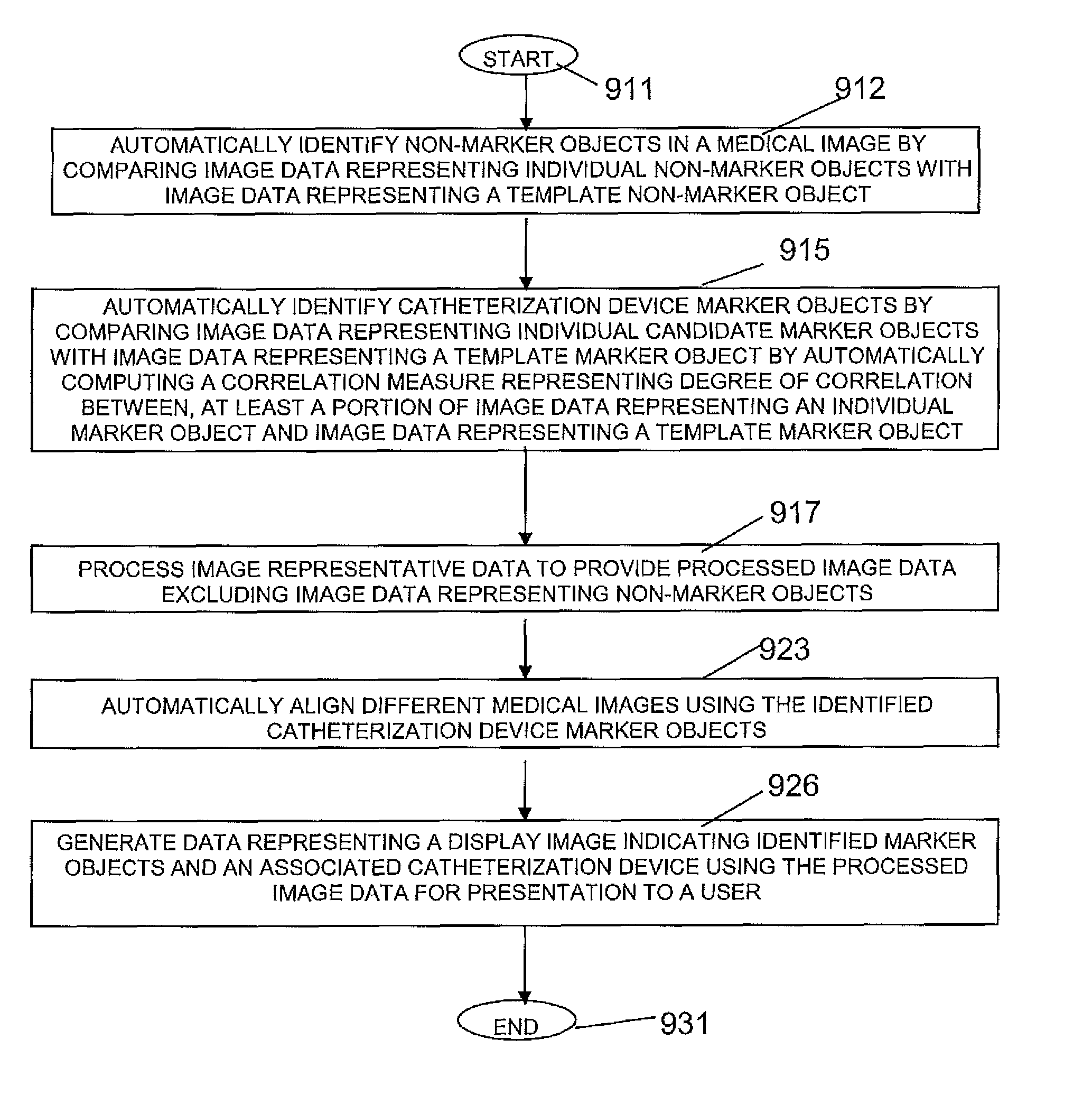
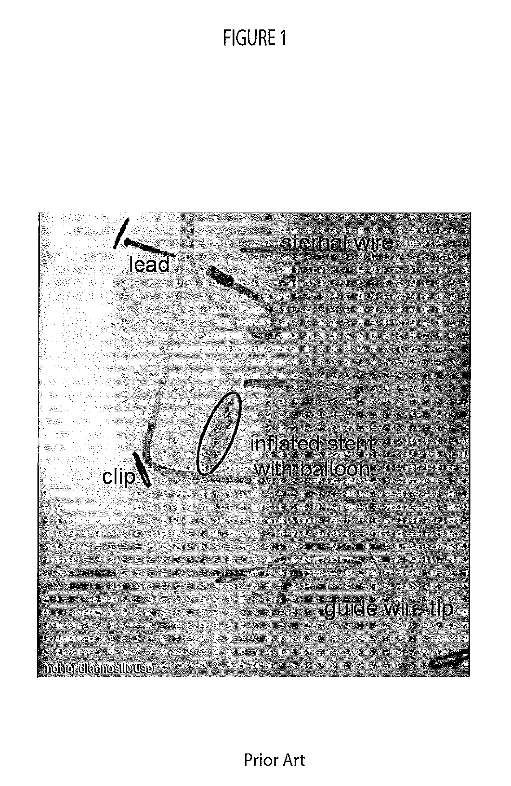
[0015]A system automatically detects balloon markers in an angiogram image that also contains other high contrast objects by detecting and labelling unwanted high contrast objects and by employing a marker object search. The system improves image quality using multiple images that are registered (aligned) based on the location of balloon marker spheres and averaged, for example. The system advantageously substantially increases CNR (Contrast to Noise Ratio) and enhances visibility of stent struts and the boundaries of a stent. A stent as used herein comprises an object such as a medical instrument or device that is used invasively within patient anatomy such as for a PTCA (Percutaneous Transluminal Coronary Angioplasty) procedure, for example. A marker sphere as used herein comprises a sphere or another radio-opaque object used to mark position or boundaries of a stent or invasive instrument.

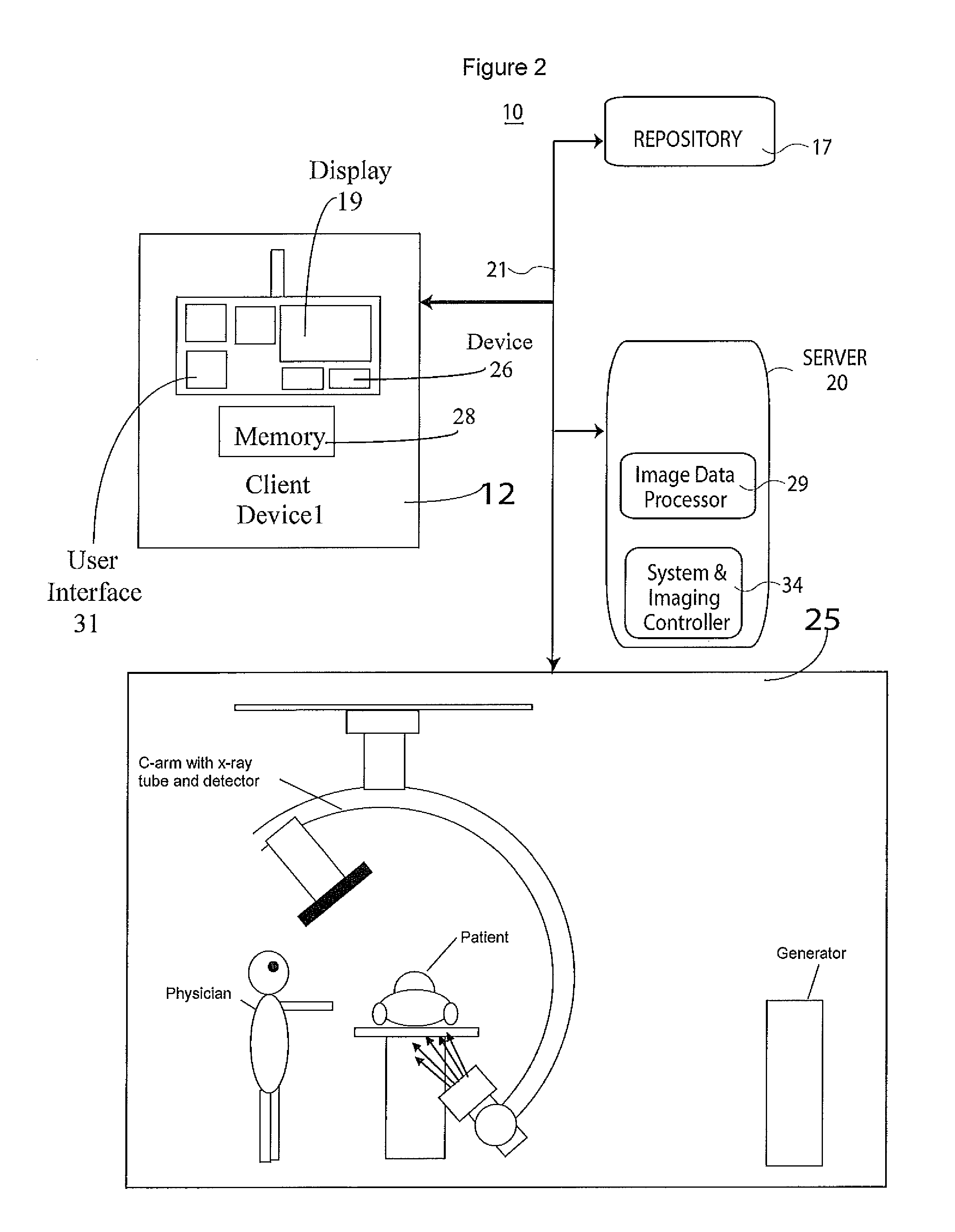
[0016]FIG. 2 shows medical image data processing system 10 for automatically identifying a c...


PUM


Abstract

A medical image data processing system automatically identifies a catheterization device including marker objects for use in identifying the catheterization device in a medical image for Angiography or another medical procedure. The system includes an image data processor that automatically identifies non-marker objects in a medical image by comparing image data representing individual non-marker objects with image data representing a template non-marker object. The processor automatically identifies catheterization device marker objects by comparing image data representing individual candidate marker objects with image data representing a template marker object and by processing image representative data to provide processed image data excluding image data representing non-marker objects. A user interface generates data representing a display image indicating identified marker objects and an associated catheterization device using the processed image data for presentation to a user.

Description

[0001]This is a non-provisional application of provisional application Ser. No. 61 / 219,034 filed 22 Jun. 2009, by Markus Lendl.FIELD OF THE INVENTION[0002]This invention concerns a medical image data processing system for automatically identifying a catheterization device including marker objects for use in identifying the catheterization device in a medical image for Angiography or another medical procedure.BACKGROUND OF THE INVENTION[0003]It is desirable to provide an angiographic image showing a stent or other interventional instrument with precision and good visibility to enable evaluation of stent placement. The location and inflation status of a stent are of particular interest. A stent consists of a mesh of fine wires. Further, for the visualisation of stents during placement usually an X-ray based angiographic system is used. Displaying stent struts is a challenge when a patient is large and / or steep imaging angles are involved. Quality of images identifying stent location p...

Claims


Application Information

Patent Timeline
Patent Type & Authority Patents(United States)
IPC IPC(8): G06K9/00
CPCG06K9/3216G06T7/0081G06K2009/3225G06K2209/057G06T2207/10081G06T2207/30021G06T7/11G06V10/245G06V2201/034
Inventor LENDL, MARKUS
Owner SIEMENS HEALTHCARE GMBH
Why Eureka
Try Eureka