
Microelectromechanical gyroscope with continuous self-test function

a microelectromechanical and self-testing technology, applied in the direction of acceleration measurement using interia forces, speed measurement using gyroscopic effects, devices using electric/magnetic means, etc., can solve the problem that the self-testing function cannot be exploited continuously or simultaneously with normal operation, and is impossible to achieve the effect of being practical or even impossibl

Active Publication Date: 2013-06-11
STMICROELECTRONICS SRL
View PDF11 Cites 22 Cited by
  • Summary
  • Abstract
  • Description
  • Claims
  • Application Information

AI Technical Summary

Benefits of technology

The patent describes a device that includes a microelectromechanical gyroscope and a sensing device that can detect movement of the scope. The sensing device is designed to distinguish between movement of the body and movement of the sensing mass, which is introduced by a biasing force applied by an actuator. The device can be used in various devices such as palm-top computers, laptops, cell phones, and digital cameras, to detect movement. The testing process described in the patent is also provided. The technical effect of this invention is to provide a more efficient and practical way to test the operation of microelectromechanical gyroscopes.

Problems solved by technology

It is noted that the known self-test process described above requires that the gyroscope be at rest, which is often impractical or even impossible, and that the self-test function cannot be exploited continuously or simultaneously with normal operation.

Method used


Image

  • Microelectromechanical gyroscope with continuous self-test function
  • Microelectromechanical gyroscope with continuous self-test function
  • Microelectromechanical gyroscope with continuous self-test function

Examples


Embodiment Construction

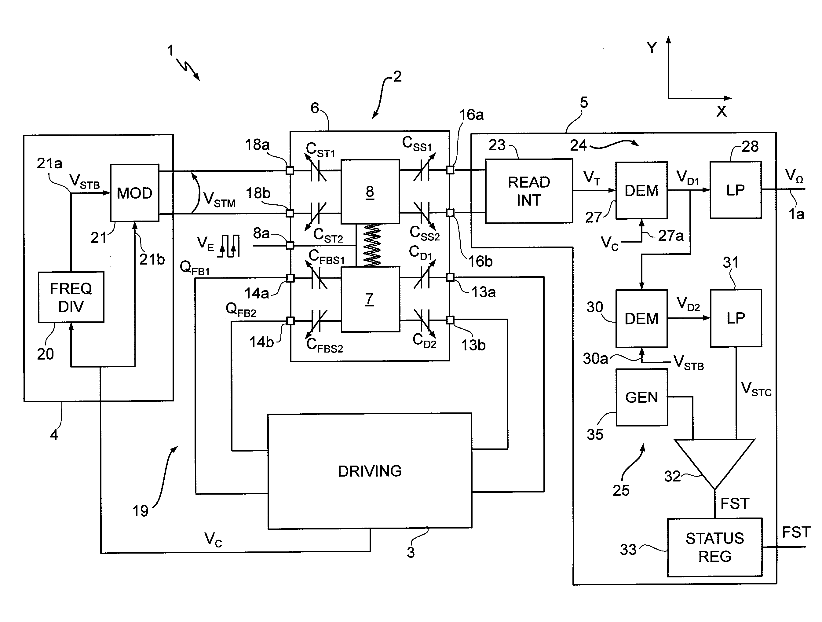
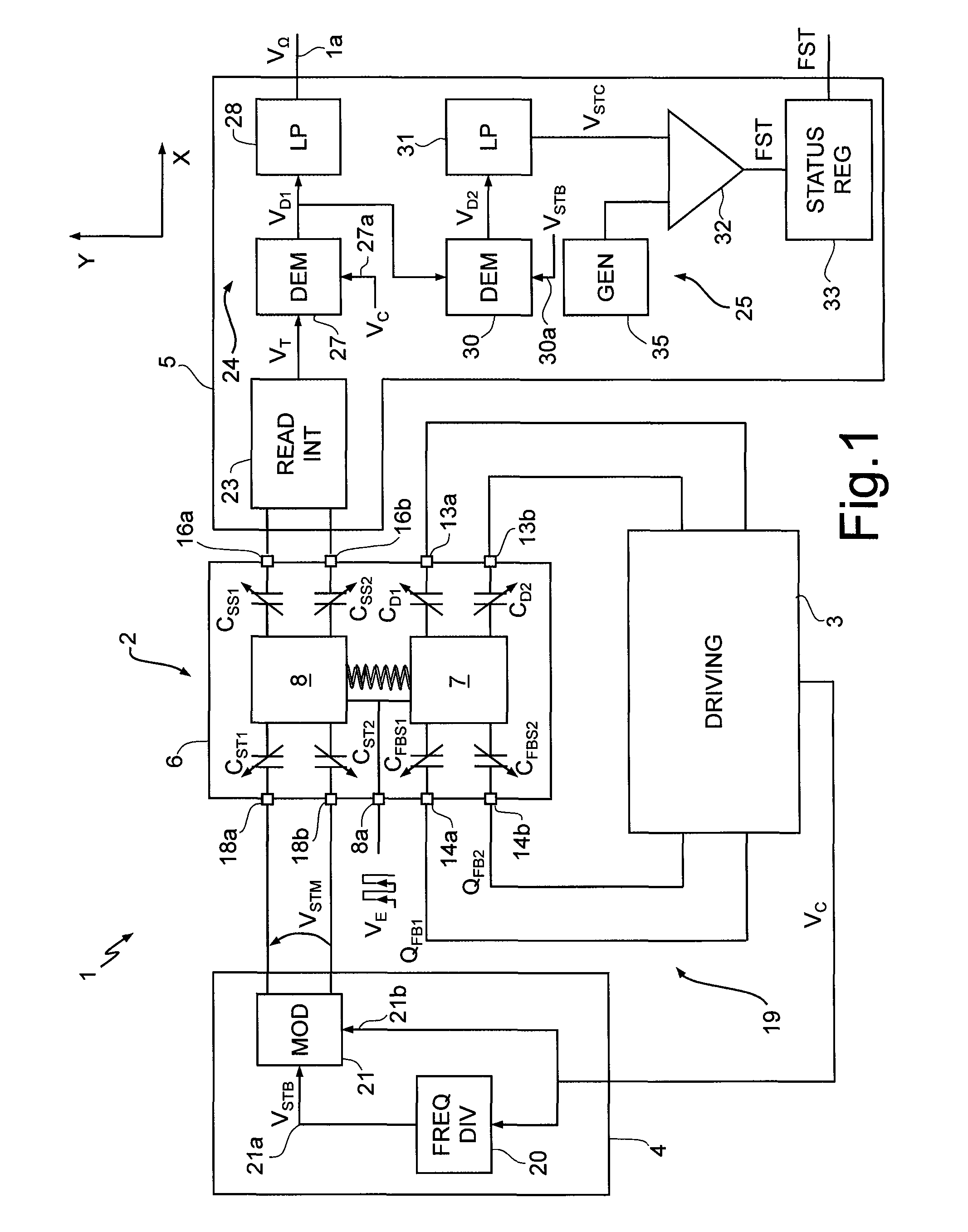
[0028]FIG. 1 is a schematic illustration of a microelectromechanical gyroscope 1, which comprises a microstructure 2, made of semiconductor material, a driving device 3, a self-test actuator 4, and a sensing device 5.

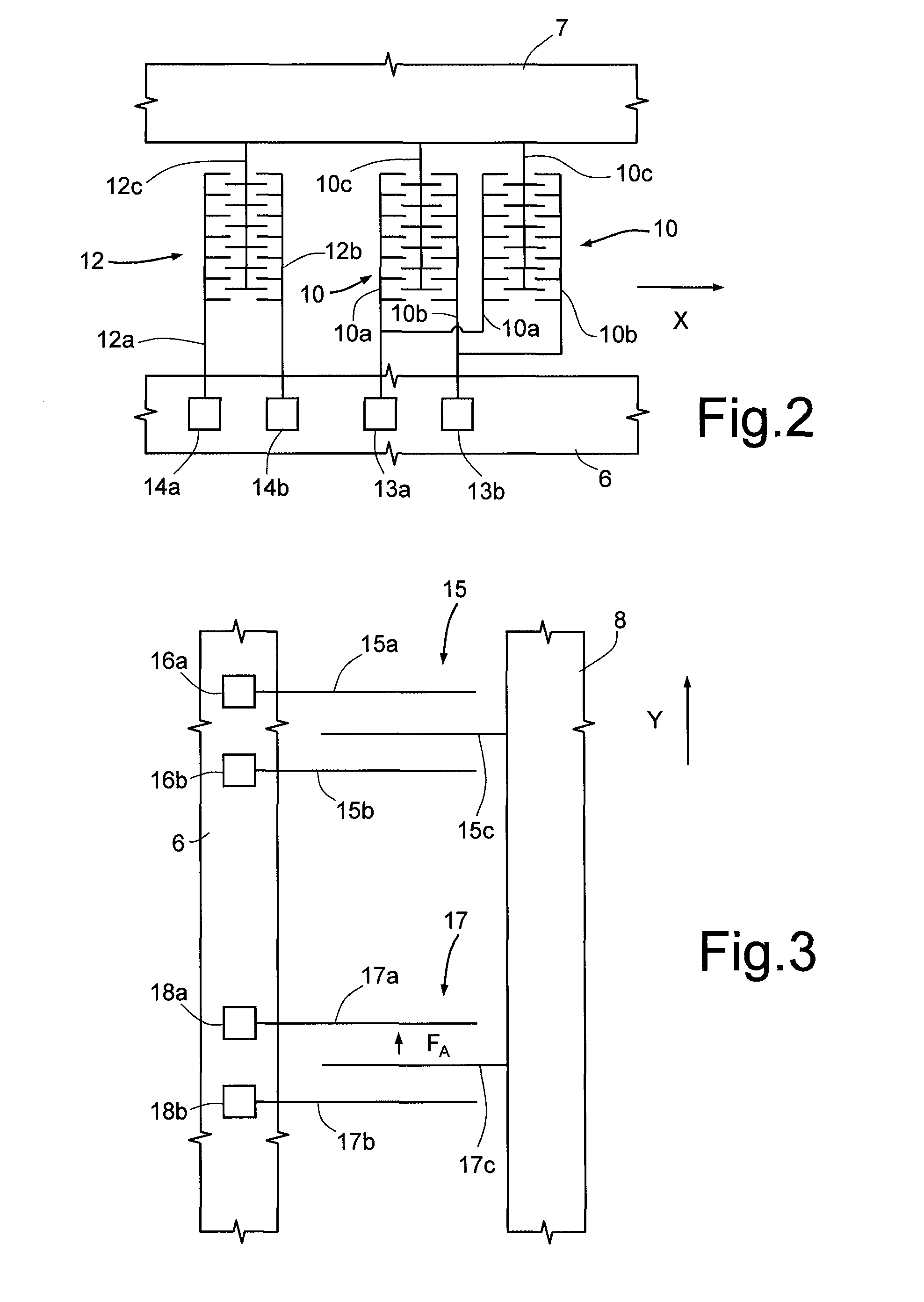
[0029]The microstructure 2 is made of semiconductor material and comprises a fixed structure 6, a driving mass 7, and at least one sensing mass 8. For reasons of simplicity, in the embodiment illustrated herein reference will be made to the case of a uniaxial gyroscope, in which only one sensing mass 8 is present. The ensuing description applies, however, also to the case of multiaxial gyroscopes, which comprise two or more sensing masses for detecting rotations according to respective independent axes.

[0030]The driving mass 7 is elastically connected by suspensions (not shown) to the fixed structure 6 so as to be oscillatable about a rest position according to a translational or rotational degree of freedom.

[0031]The sensing mass 8 is mechanically coupled to the drivin...


PUM


Abstract

A microelectromechanical gyroscope includes a body and a sensing mass, which is movable with a degree of freedom in response to rotations of the body about an axis. A self-test actuator is capacitively coupled to the sensing mass for supplying a self-test signal. The capacitive coupling causes, in response to the self-test signal, electrostatic forces that are able to move the sensing mass in accordance with the degree of freedom at an actuation frequency. A sensing device detects transduction signals indicating displacements of the sensing mass in accordance with the degree of freedom. The sensing device is configured for discriminating, in the transduction signals, spectral components that are correlated to the actuation frequency and indicate the movement of the sensing mass as a result of the self-test signal.

Description

BACKGROUND[0001]1. Technical Field[0002]The present invention relates to a microelectromechanical gyroscope with continuous self-test function, and to a method for controlling a microelectromechanical gyroscope.[0003]2. Description of the Related Art[0004]As is known, the use of microelectromechanical systems (MEMS) has increasingly spread in various technological sectors and has yielded encouraging results especially in providing inertial sensors, micro-integrated gyroscopes, and electromechanical oscillators for a wide range of applications.[0005]MEMS systems of this type are usually based upon microelectromechanical structures comprising at least one mass, connected to a fixed body (stator) through springs and movable with respect to the stator according to pre-set degrees of freedom. The movable mass and the stator are capacitively coupled through a plurality of respective comb-fingered and mutually facing electrodes so as to form capacitors. The movement of the movable mass wit...

Claims


Application Information

Patent Timeline
Patent Type & Authority Patents(United States)
IPC IPC(8): G01C19/56
CPCG01P21/00G01C19/56
Inventor DONADEL, ANDREAPRANDI, LUCIANOCAMINADA, CARLO
Owner STMICROELECTRONICS SRL
Learn More