Work vehicle having drive wheels

a technology of transmission system and drive wheel, which is applied in the direction of electric propulsion mounting, jet propulsion mounting, hoisting equipment, etc., can solve the problem that the connecting plate may suffer an elastic deformation in the bending direction, and achieve the effect of high accuracy

Active Publication Date: 2013-06-11
KUBOTA CORP
View PDF6 Cites 31 Cited by
  • Summary
  • Abstract
  • Description
  • Claims
  • Application Information

AI Technical Summary

Benefits of technology

[0008]Therefore, it is desirable to provide a work vehicle structure in which the positional relationship between the output system of the engine and the input system of the transmission is retained with high accuracy.
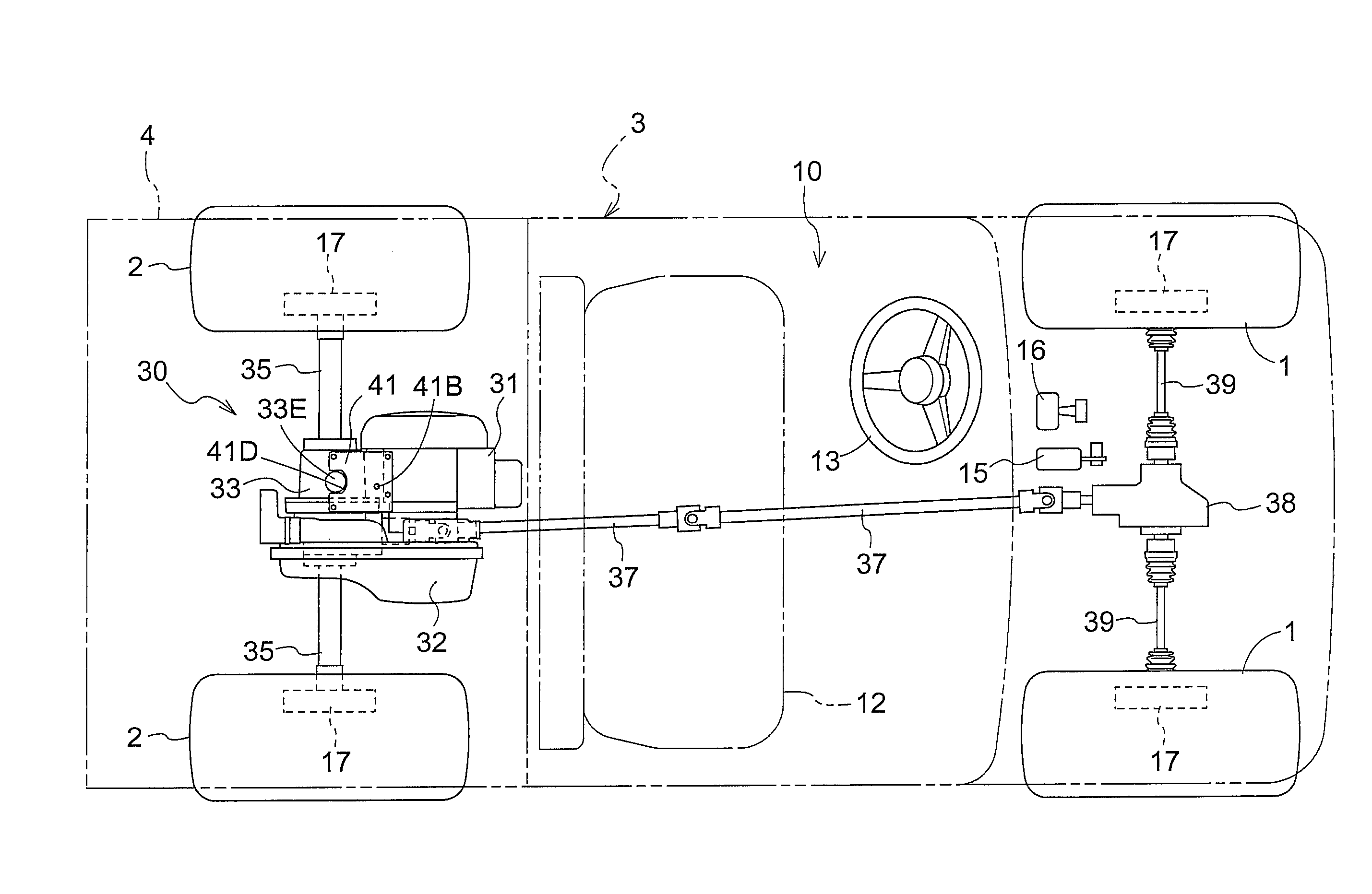
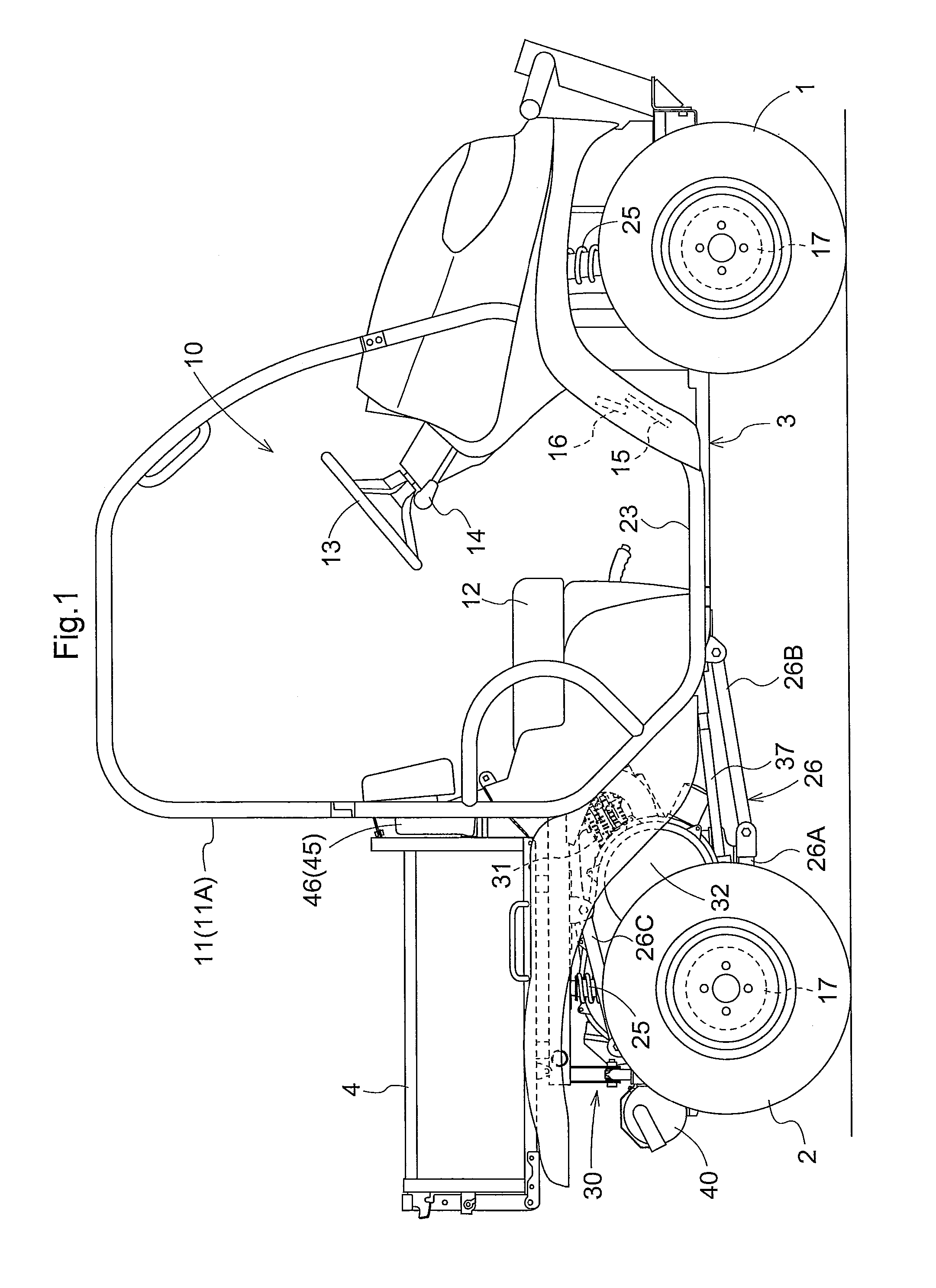
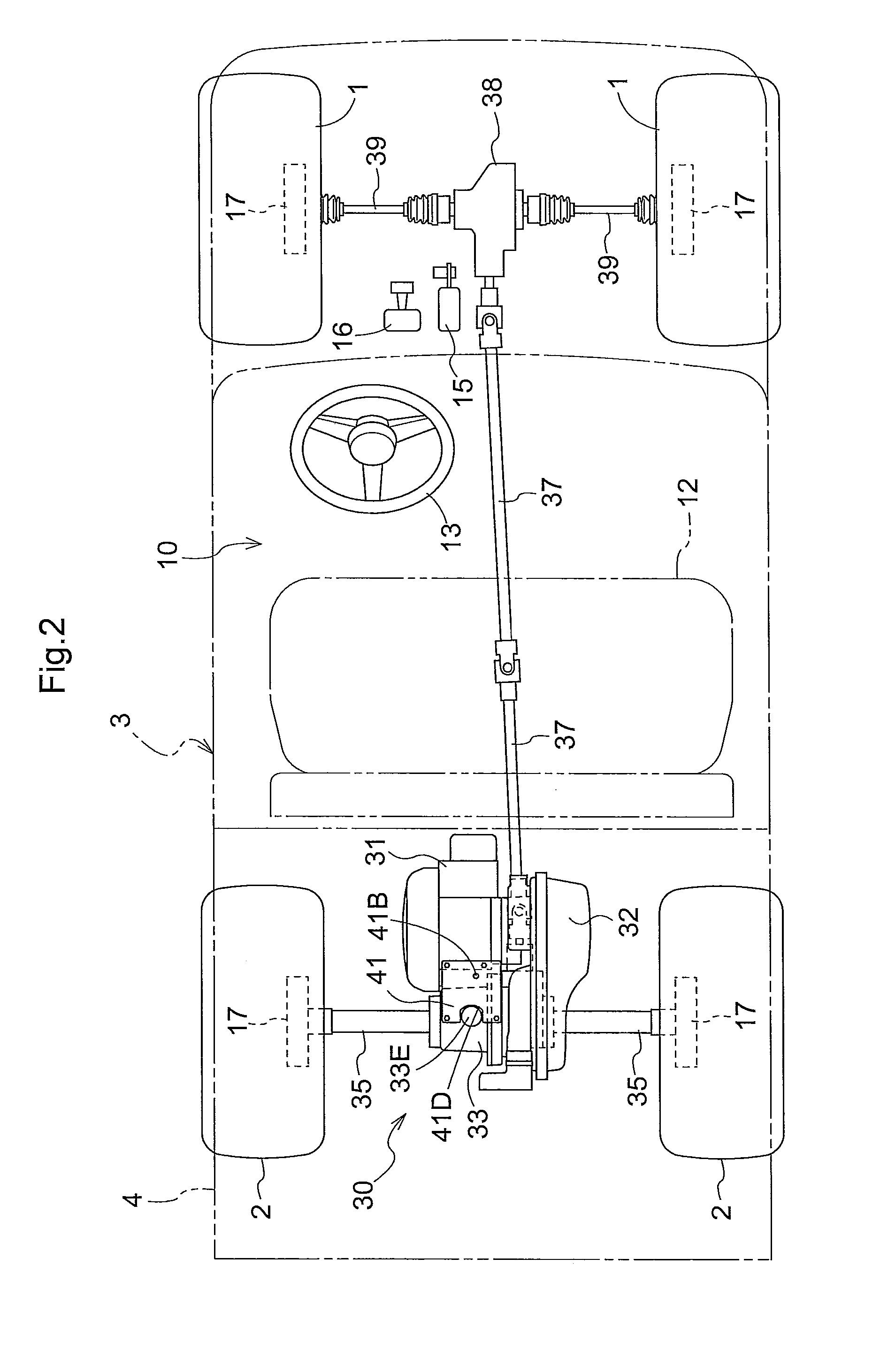
[0010]According to this configuration, the connecting plate is disposed on the upper part of the engine and the upper part of the transmission in such a manner that the cover portion thereof covers the space. When the connecting plate is disposed in this manner, the cover portion as a face of the connecting plate is arranged in parallel with an axis of the output shaft of the engine and an axis of the input shaft of the transmission. Therefore, even when a force from the CVT may act in a direction that makes the output shaft of the engine and the input shaft of the transmission closer to or away from each other, since the connecting plate is arranged in a posture in which the connecting plate is not likely to suffer the elastic deformation, a displacement in the positions between the engine and the transmission (transmission case) can be prevented. In addition, since the connecting plate is disposed above the area of the electric component, even when the work vehicle is washed or it rains hard, the connecting plate prevents water from entering the electric component.
[0011]As a result, the work vehicle is obtained in which the positional relationship between the output system of the engine and the output system of the transmission can be retained with high accuracy, and the electric component disposed near the engine can be protected.

Problems solved by technology

However, in the case of the connecting plate oriented orthogonally to an axis of the output shaft and an axis of the input shaft, there is a possibility that the connecting plate may suffer an elastic deformation in a bending direction, due to a tensile force exerted in an endless belt of belt-type CVT between the output shaft and the input shaft.
Accordingly, when the work vehicle is washed or it rains hard, water may enter the electric component and cause a malfunction.

Method used


Image

  • Work vehicle having drive wheels
  • Work vehicle having drive wheels
  • Work vehicle having drive wheels

Examples


embodiment

(Effect of Embodiment)

[0073]As described above, according to the present invention, the cooling air supplied to the CVT case 64 is brought into contact with the driving pulley 61, the driven pulley 62, and the endless belt 63, to thereby cool them. In addition, since the cooling air is supplied from the case main body 64A of the CVT case 64 and the cooling air is discharged from the discharge part 64F of the case main body 64A, even during an operation of removing the cover member 64B, it is not necessary to remove a duct for supplying the cooling air, a duct for exhausting the cooling air and the like, and thus the operation is facilitated.

[0074]In the case main body 64A, the bulging part 64D bulging in a side opposite to the cover member 64B (the transmission case 33 side) is formed, and the discharge part 64F is formed in the bulging part 64D. In the discharge part 64F, along with the rotation of the driven pulley 62, the wind pressure acting in a tangential direction from the up...


PUM


Abstract

A work vehicle having drive wheels includes: an engine having an output shaft oriented in a transverse direction of a vehicle body; a transmission having an input shaft oriented in the transverse direction, which includes a transmission case arranged next to the engine in a front-rear direction of the vehicle body; and a CVT which extends between a lateral side of the engine and a lateral side of the transmission case and is configured to transmit a driving force from the output shaft to the input shaft. A connecting plate is configured to connect an upper part of the engine and an upper part of the transmission case and has a cover part. An electric component is disposed in a space defined by the engine, the transmission case and the connecting plate and is covered by the cover part from above.

Description

BACKGROUND[0001]1. Field of the Invention[0002]The present invention relates to a work vehicle having a traveling transmission system in which a driving force of an output shaft of an engine is transmitted from a continuously variable transmission device (CVT) to an input shaft of a transmission case, and a driving force of the transmission case is transmitted to wheels.[0003]2. Description of the Related Art[0004]Japanese Unexamined Patent Application Publication No. 2006-82631 describes one example of the above-described conventional work vehicle in which an engine and a transmission are arranged next to each other, and on a lateral side of the engine and transmission, a belt converter is disposed. A lateral face of the engine and a lateral face of the transmission are joined with a connecting plate to thereby unify the engine and the transmission, and thus a positional relationship between the output shaft of the engine and the input shaft of the transmission is fixed.[0005]In th...

Claims


Application Information

Patent Timeline
Patent Type & Authority Patents(United States)
IPC IPC(8): B60K17/22
CPCB60K5/04B60K11/06B60K17/08B60K17/344F16H57/0416F16H57/0489B60Y2200/141B60Y2200/22
Inventor BESSHO, HIROKIKAWAMURA, SHOICHIROFUJIWARA, KOJIMURAKAWA, MASATAKE
Owner KUBOTA CORP
Why Eureka
Try Eureka