

Auto-selecting two-ratio transmission
Patent Information
- Authority / Receiving Office
- US · United States
- Patent Type
- Patents(United States)
- Current Assignee / Owner
- LITENS AUTOMOTIVE INC
- Publication Date
- 2013-06-11
Smart Images
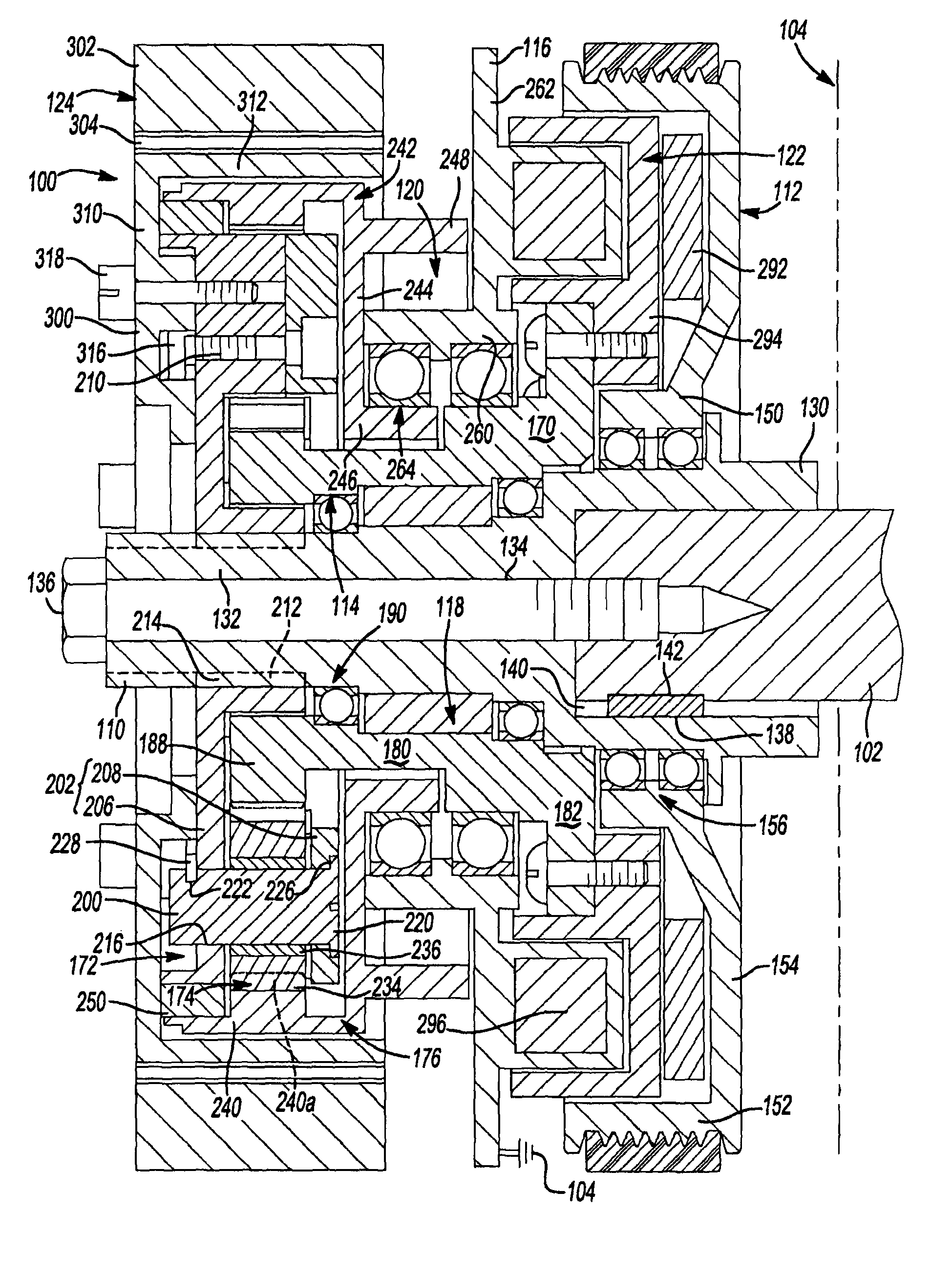
Figure 1 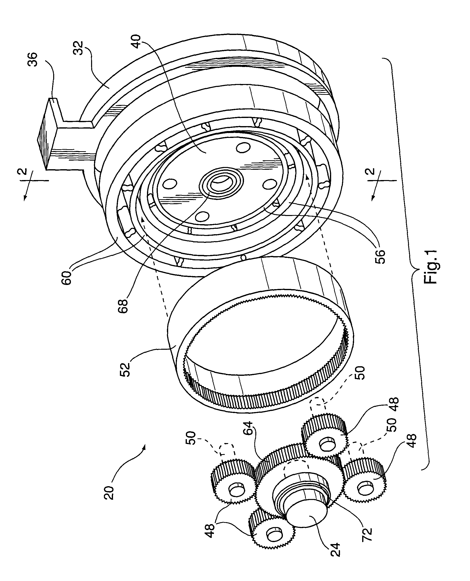
Figure 2 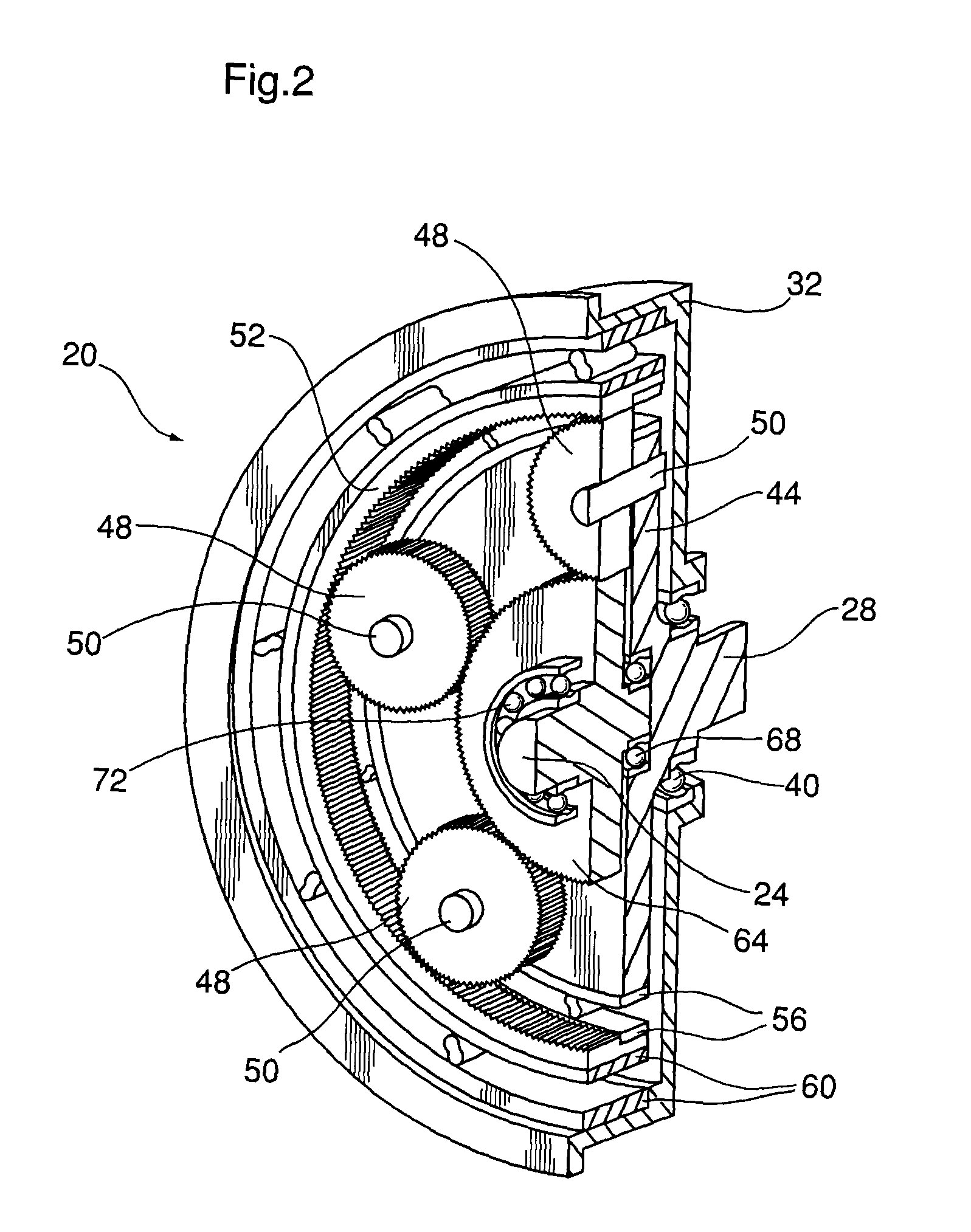
Figure 3
Abstract
Description
CROSS-REFERENCE TO RELATED APPLICATIONS
[0001] This application is a 371 of PCT / CA2009 / 000438 filed Apr. 06, 2009, which claims the benefit of U.S. Provisional No. 61 / 042,439 filed Apr. 4, 2008.INTRODUCTION
[0002] The present disclosure generally relates to an auto-selecting two-ratio transmission and more particularly to a pulley assembly with an auto-selecting two-ratio transmission.
[0003] Transmissions which provide different rotation ratios between an input and an output shaft are well known. Depending upon the rotation ratio between the input and output shafts, the torque transferred from the input shaft to the output shaft through the transmission can be increased or decreased and the rotation speed of the output shaft is correspondingly decreased or increased relative to the rotation speed of the input shaft.
[0004] It is also known to have a transmission which can provide more than one ratio between the input and the output of the transmission. The desired ratio can be selected fro...